Conductivity Apparatus
Conductivity Apparatus
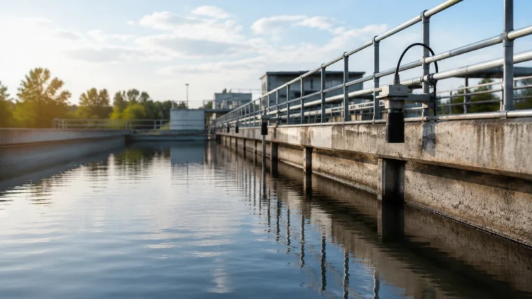
In industrial process control, a conductivity apparatus serves as a critical diagnostic tool for monitoring the ionic concentration of liquids and detecting the presence of conductive media within tanks and pipelines. While often associated with laboratory water analysis, industrial-grade conductivity apparatus is engineered to withstand the rigors of chemical processing, wastewater treatment, and food production. Understanding the underlying physics of electrolytic conduction is essential for selecting the correct instrumentation and ensuring long-term reliability in automated systems.
Conductivity measurement is fundamentally the measurement of a liquid's ability to conduct an electrical current. This capability depends on the concentration of ions, their mobility, and the temperature of the solution. In the context of level measurement, conductivity-based sensors act as point level switches, utilizing the liquid itself to complete an electrical circuit between electrodes.
Measurement Principles of Conductivity Apparatus
To effectively deploy a conductivity apparatus, engineers must distinguish between metallic conduction and electrolytic conduction. In metals, electrons carry the charge. In liquids, the charge is carried by cations (positively charged ions) and anions (negatively charged ions).
Ohm’s Law and Conductance
The basic principle follows Ohm’s Law ($V = I \times R$), where $V$ is voltage, $I$ is current, and $R$ is resistance. Conductance ($G$) is the reciprocal of resistance ($G = 1/R$) and is measured in Siemens (S). In industrial applications, we typically measure in milliSiemens per centimeter (mS/cm) or microSiemens per centimeter (µS/cm).
The Cell Constant (K)
The geometry of the conductivity apparatus significantly influences the measurement. The cell constant ($K$) is defined as the ratio of the distance ($L$) between the electrodes to the cross-sectional area ($A$) of the electrodes ($K = L/A$).
* Low Cell Constants (e.g., K=0.1): Used for high-purity water where ions are scarce.
* High Cell Constants (e.g., K=10): Used for concentrated chemicals or seawater where ion density is high.
Temperature Compensation
Conductivity is highly temperature-dependent. As temperature increases, fluid viscosity typically decreases, increasing ionic mobility. Most industrial conductivity apparatus includes an integrated Resistance Temperature Detector (RTD), such as a Pt100 or Pt1000, to provide automatic temperature compensation (ATC), usually referenced to 25°C.
Types of Industrial Conductivity Instruments
Depending on the application—whether it is monitoring the concentration of a cleaning solution or detecting a high-level alarm in a sump—different configurations of conductivity apparatus are utilized.
Contacting Conductivity Sensors
These sensors feature two or more electrodes in direct contact with the process fluid. They are highly accurate for low-conductivity applications, such as deionized water or boiler condensate. However, they are susceptible to fouling, polarization, and corrosion if used in aggressive or high-solids environments.
Inductive (Toroidal) Conductivity Sensors
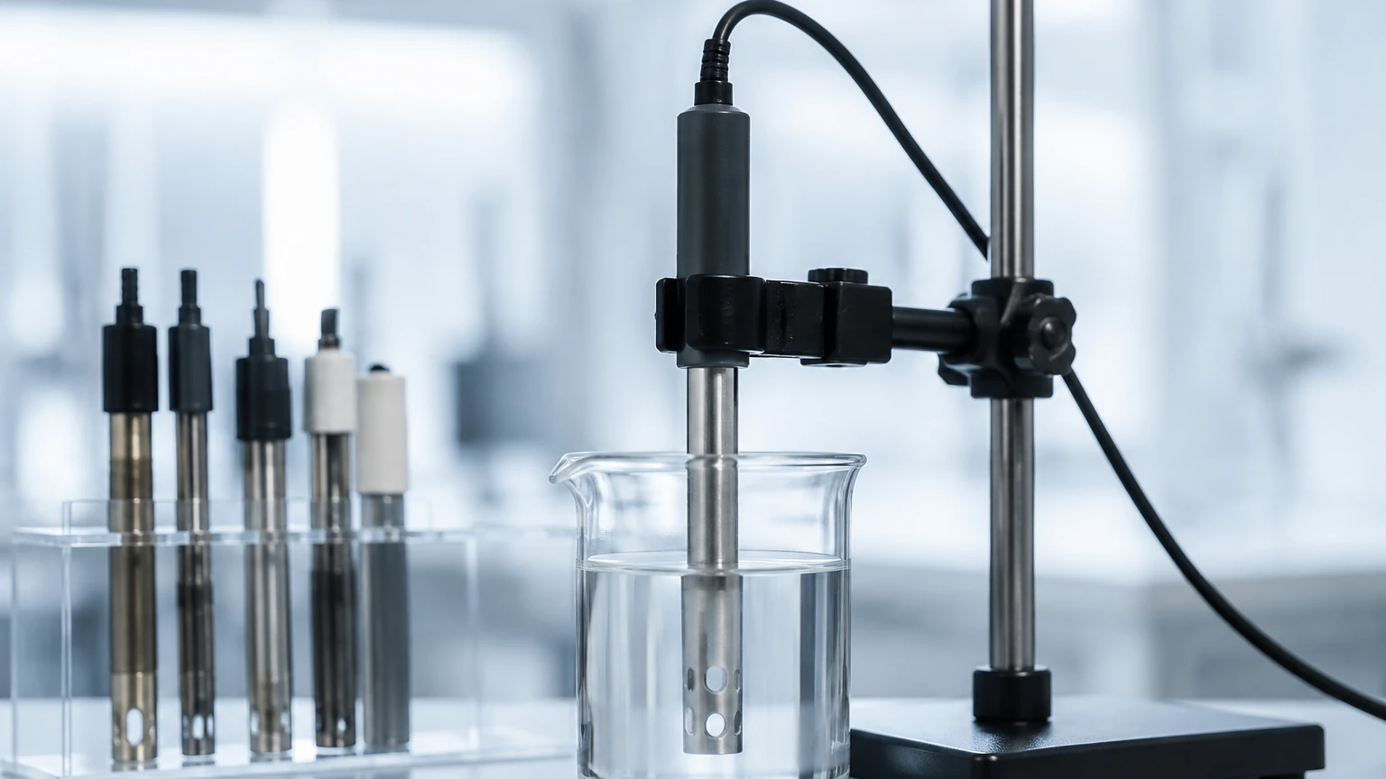
Inductive sensors use two wire-wound metal toroids encapsulated in a plastic or ceramic housing. One coil induces an alternating current in the surrounding liquid, and the second coil measures the magnitude of this current. Because there are no exposed electrodes, this type of conductivity apparatus is ideal for highly corrosive acids, bases, and slurries that would otherwise coat or corrode contacting electrodes.
Conductivity Level Switches
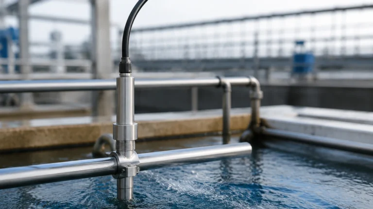
In level control, the conductivity apparatus functions as a limit switch. A low-voltage AC signal is applied to a probe. When the conductive liquid reaches the probe, it completes the circuit to the tank wall (if metal) or a reference electrode. This change in state triggers a relay to start or stop pumps or activate alarms. This is a robust, low-cost solution for many water-based applications.
Selection Criteria for Conductivity Apparatus
Selecting the appropriate instrument requires a detailed analysis of the process fluid and the physical environment. Engineers should consult the Main Page of specialized manufacturers to compare technical specifications against their specific project requirements.
| Criteria | Contacting Sensors | Inductive (Toroidal) Sensors | Conductivity Level Probes |
| :— | :— | :— | :— |
| Conductivity Range | 0.01 µS/cm to 10 mS/cm | 100 µS/cm to 2,000 mS/cm | Binary (Detects presence) |
| Fluid Cleanliness | Must be clean/non-coating | Can handle slurries/solids | Can handle moderate coating |
| Chemical Resistance | Limited by electrode metal | Excellent (PEEK, PFA, PP) | High (SS316, Hastelloy) |
| Maintenance | High (Cleaning required) | Very Low | Low to Moderate |
| Primary Application | Pure water, RO systems | Acid/Base concentration, CIP | Pump control, Overfill protection |
Material Compatibility
The wetted parts of the conductivity apparatus must be chemically inert relative to the process fluid. Common electrode materials include Stainless Steel 316L, Graphite, Titanium, and Hastelloy C. For the insulating body, materials like Polypropylene (PP), PTFE (Teflon), and PEEK are standard. PEEK is often preferred in food and beverage applications due to its high temperature rating and mechanical strength.
Installation Considerations
Correct installation is paramount to the accuracy and longevity of a conductivity apparatus. Failure to account for hydraulic conditions or electrical interference can lead to erratic readings.
1. Avoid Air Pockets: Sensors must be installed in a location where they are always fully submerged. In horizontal pipes, mount the sensor on the side rather than the top to prevent air entrapment.
2. Flow Direction: For contacting sensors, the flow should enter the open end of the electrode assembly to ensure constant refreshment of the sample and to minimize the buildup of debris.
3. Grounding and Interference: Conductivity measurements use low-level electrical signals. Ensure the instrument is properly grounded and that signal cables are shielded and separated from high-voltage power lines to prevent electromagnetic interference (EMI).
4. Pipe Diameter: For inductive sensors, the magnetic field extends beyond the sensor body. If the sensor is installed too close to a pipe wall (especially a metal wall), it can cause "wall effects" that distort the reading. Manufacturers typically specify a minimum clearance, often 10mm to 30mm depending on the sensor size.
Limitations and Common Challenges
While robust, conductivity apparatus is not a universal solution for all liquid measurement tasks.
* Non-Conductive Liquids: Conductivity sensors cannot detect or measure hydrocarbons, oils, or ultrapure solvents that do not contain ions. In these cases, radar or ultrasonic level meters are required.
* Polarization: When using DC current, ions can migrate to the electrodes and create a capacitive layer that increases resistance, leading to false low readings. Industrial conductivity apparatus uses AC current to prevent this effect.
* Fouling and Scaling: In wastewater or hard water applications, calcium carbonate or biological films can coat the electrodes. This coating acts as an insulator, reducing the measured conductivity. Regular cleaning or switching to an inductive (non-contacting) sensor is necessary in these environments.
* Bubbles and Aeration: Air is a perfect insulator. If the liquid is highly aerated or turbulent, the conductivity apparatus will report a lower-than-actual conductivity or intermittent level signals.
Maintenance and Calibration Procedures
To maintain the integrity of the data, a regular maintenance schedule should be established. For contacting sensors, this involves physical inspection of the electrodes for pitting or coating.
Calibration Standards
Calibration is performed using standard solutions with known conductivity values (e.g., 1413 µS/cm or 12.88 mS/cm). It is critical that the calibration solution is fresh, as exposure to atmospheric CO2 can alter the conductivity of low-range standards.
Verification
In many regulated industries, such as pharmaceuticals, a "loop check" is required. This involves using a precision resistor box in place of the sensor to verify that the transmitter correctly interprets the resistance and converts it to the expected conductivity value.
Frequently Asked Questions (FAQ)
Q: Can I use a conductivity apparatus to measure the level of oil?
A: No. Most oils are non-conductive (dielectric). A conductivity probe will not detect the interface. For oil level measurement, consider using a guided wave radar or a capacitive level sensor.
Q: How often should I calibrate my conductivity sensor?
A: Calibration frequency depends on the application. In stable, clean water applications, every six months may suffice. In aggressive chemical processes or wastewater, monthly or even weekly verification may be necessary.
Q: What is the difference between a 2-electrode and a 4-electrode sensor?
A: A 2-electrode sensor is simpler and suitable for low conductivity. A 4-electrode sensor uses two electrodes to drive the current and two to measure the voltage drop; this design eliminates the effects of electrode polarization and lead wire resistance, making it much more accurate for high-conductivity measurements.
Q: Can conductivity be used to identify a specific chemical?
A: Conductivity is a non-specific measurement. It tells you the total ionic content but not which ions are present. However, if you know you are only mixing water and Sulfuric Acid, conductivity can be used to accurately determine the concentration of that specific acid.
Conclusion
The conductivity apparatus remains a cornerstone of industrial liquid analysis and point level detection due to its simplicity and reliability. By understanding the relationship between cell constants, temperature compensation, and fluid properties, engineers can implement solutions that minimize maintenance and maximize process uptime. For those integrating these sensors into broader automation frameworks, reviewing the comprehensive range of measurement technologies on the Main Page is a recommended step to ensure all process variables—from level to liquid quality—are accurately monitored.