Coriolis Mass Flow Sensors
Coriolis Mass Flow Sensors
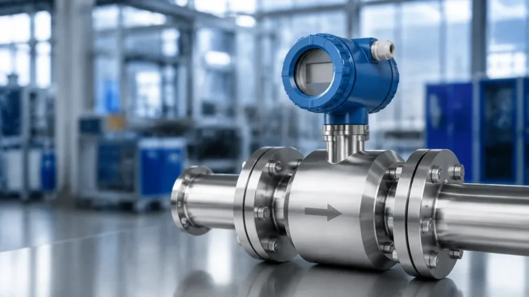
In the landscape of industrial process control, the ability to measure mass directly rather than calculating it from volume and density is a significant advantage. Coriolis mass flow sensors represent the pinnacle of flow measurement technology, providing high accuracy and multi-parameter data. Unlike volumetric flow meters, which are susceptible to errors caused by changes in temperature, pressure, and fluid composition, Coriolis meters provide a direct measurement of the mass of the fluid passing through the system.
This guide explores the engineering principles, selection criteria, and installation requirements for Coriolis mass flow sensors, serving as a technical reference for engineers integrating these devices into industrial automation and inventory management systems.
Measurement Principles of Coriolis Mass Flow Sensors
To understand why Coriolis mass flow sensors are favored in critical applications, one must first understand the physical phenomenon they utilize: the Coriolis effect. This effect describes the inertial force acting on an object that is in motion within a frame of reference that is rotating.
The Coriolis Effect in a Tube
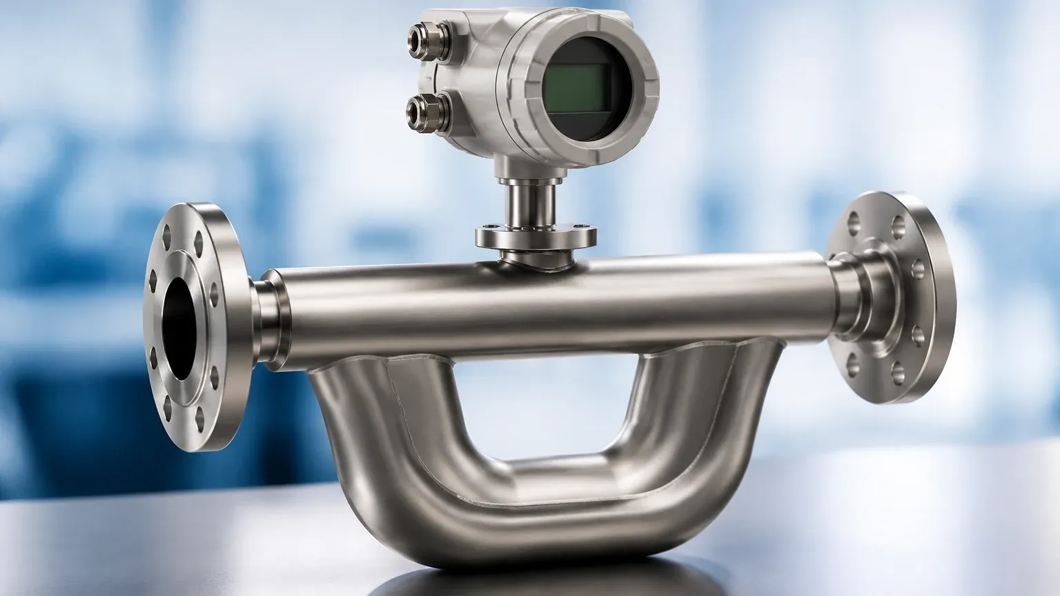
In an industrial sensor, the "rotating frame" is replaced by an oscillating measuring tube. The sensor typically consists of one or two vibrating tubes, usually made of stainless steel or specialized alloys. An internal drive coil causes the tube(s) to vibrate at their natural resonant frequency.
When there is no flow, the tube vibrates uniformly. However, when a fluid (liquid or gas) begins to flow through the tube, the fluid's mass in motion resists the vibration. According to the laws of physics, the fluid entering the sensor resists being pushed upward (or downward) by the tube's vibration, while the fluid leaving the sensor resists being slowed down. This creates a twisting force, or a "phase shift," between the inlet and outlet sides of the tube.
Direct Mass and Density Measurement
The degree of this twist or phase shift is directly proportional to the mass flow rate. Sensors located at the inlet and outlet of the tube detect this time difference (measured in microseconds). Because the measurement is based on inertia, it is independent of the fluid's viscosity, conductivity, or flow profile.
Simultaneously, the sensor measures the resonant frequency of the tube's vibration. This frequency changes depending on the mass of the tube and the fluid inside it. Since the volume of the tube is constant, the frequency can be used to calculate the fluid's density in real-time. This dual-capability—measuring both mass flow and density—makes Coriolis mass flow sensors uniquely versatile.
Key Evaluation Criteria for Industrial Applications
When evaluating Coriolis mass flow sensors for a specific process, several technical parameters must be prioritized to ensure long-term reliability and accuracy.
Accuracy and Repeatability
Coriolis meters are known for exceptional accuracy, often reaching ±0.1% or even ±0.05% of the flow rate for liquids. For gases, accuracy is typically lower, ranging from ±0.35% to ±0.5%. It is essential to distinguish between "percentage of rate" and "percentage of full scale," as Coriolis sensors maintain their accuracy over a wide turndown ratio (often 100:1).
Material Compatibility and Pressure Drop
The measuring tubes are the primary wetted parts. Standard sensors use 316L stainless steel, but for corrosive chemicals, materials like Hastelloy C-22 or Tantalum may be required. Additionally, the geometry of the tube (U-shape vs. straight tube) impacts the pressure drop. U-shaped tubes generally offer higher sensitivity but may cause a higher pressure drop compared to straight-tube designs.
Multi-Variable Output
Modern transmitters paired with Coriolis sensors can output multiple variables simultaneously via 4-20mA, HART, Modbus, or Profibus. These include:
* Mass flow rate
* Density
* Temperature (via an internal RTD used for compensation)
* Calculated volume flow
* Totalized mass
Practical Selection Table
The following table provides a general comparison of common Coriolis sensor configurations used in industrial settings.
| Feature | Bent Tube (U-Shape) | Straight Tube |
| :— | :— | :— |
| Sensitivity | Very High | Moderate |
| Pressure Drop | Moderate to High | Low |
| Cleanability | Difficult (potential for trapping) | Excellent (Self-draining) |
| Installation Space | Requires more vertical/horizontal room | Compact, inline design |
| Vibration Resistance | Good | Excellent |
| Typical Accuracy | ±0.05% to ±0.1% | ±0.1% to ±0.2% |
| Common Applications | Custody transfer, high-precision dosing | Food & Beverage, slurries, shear-sensitive fluids |
Installation Considerations and Best Practices
While Coriolis mass flow sensors are less sensitive to flow profiles than other technologies, their performance is heavily dependent on correct mechanical installation.
Orientation and Support
* Liquids: For liquid applications, the sensor should ideally be installed with the tubes pointing downward (in a "U" shape) to prevent gas bubbles from becoming trapped. If the fluid contains solids, the tubes should point upward to prevent sediment buildup.
* Gases: For gas applications, the tubes should point upward so that any condensed moisture can drain out of the sensor.
* Mechanical Stress: The sensor must be supported by the piping, but it should not be used to pull misaligned pipes together. Excessive stress on the sensor housing can shift the zero point and degrade accuracy.
Vibration Isolation
Because Coriolis sensors rely on precise tube vibrations, external mechanical vibrations from pumps or motors can interfere with the measurement. It is recommended to install the sensor on a stable foundation and use flexible connectors or vibration-dampening mounts if the piping system is prone to high-frequency oscillation.
Zero-Point Calibration
Upon installation and under full process pressure, a "zero-point trim" must be performed. This involves filling the sensor with the process fluid, ensuring there is absolutely zero flow (using isolation valves), and then commanding the transmitter to calibrate its zero reference. This compensates for the specific stresses and orientation of the installation.
Limitations and Common Challenges
Despite their versatility, Coriolis mass flow sensors are not a universal solution for every application. Engineers should be aware of the following limitations:
1. Entrained Air/Gas: The presence of air bubbles in a liquid (slug flow) can cause the measuring tubes to vibrate erratically. While modern digital signal processing (DSP) can mitigate some of this, high levels of entrained gas will significantly increase measurement uncertainty.
2. Initial Cost: Coriolis meters are generally more expensive than electromagnetic, vortex, or ultrasonic meters. The investment is usually justified by the reduction in maintenance and the elimination of external density compensation equipment.
3. Size and Weight: Large-diameter Coriolis sensors (above 200mm or 8 inches) are extremely heavy and bulky, making them difficult to install in existing piping networks compared to compact wafer-style meters.
Integration with Level Measurement Systems
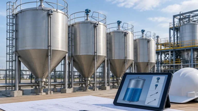
In many industrial plants, flow measurement and level measurement work in tandem. While Coriolis sensors track the movement of material through the pipes, level instruments—such as radar, ultrasonic, or hydrostatic transmitters—monitor the inventory within tanks and vessels.
For example, in a chemical blending process, Coriolis sensors ensure the precise mass of each ingredient is added to a reactor, while a radar level meter provides the primary safety redundancy to prevent overfills. Integrating these data points allows for a comprehensive mass balance analysis, which is critical for detecting leaks and optimizing production yields. For those seeking a wider range of industrial measurement solutions, including advanced radar and ultrasonic technology, you can visit the Main Page to review product options and application support.
Frequently Asked Questions (FAQs)
Q: Do Coriolis mass flow sensors require straight pipe runs upstream and downstream?
A: Generally, no. Unlike turbine or orifice plate meters, Coriolis sensors are not sensitive to flow profile disturbances like swirls or non-uniform velocity. However, it is still good practice to avoid placing them immediately after a high-vibration source like a pump.
Q: Can a Coriolis meter measure the flow of non-conductive liquids?
A: Yes. Because the measurement is based on mass and inertia, the electrical properties of the fluid (conductivity, dielectric constant) do not affect the measurement. This makes them ideal for hydrocarbons and deionized water.
Q: How often should a Coriolis sensor be recalibrated?
A: Coriolis sensors have no moving parts that wear out, making them very stable. In many non-corrosive applications, they can operate for several years without a shift in calibration. However, for custody transfer or regulated industries, annual verification is standard.
Q: What is the maximum temperature a Coriolis sensor can handle?
A: Standard models typically handle up to 200°C (392°F), but specialized high-temperature versions are available that can operate up to 350°C (662°F) using remote electronics to protect the transmitter from heat.
Conclusion
Coriolis mass flow sensors are a cornerstone of modern process engineering, offering unmatched precision and multi-variable data. By understanding the underlying physics of the Coriolis effect and adhering to strict installation guidelines regarding vibration and orientation, facilities can achieve highly reliable mass balance and process control. When combined with robust level measurement strategies, these sensors provide the data necessary for efficient, safe, and cost-effective industrial operations.