Difference Pressure Sensor
Difference Pressure Sensor
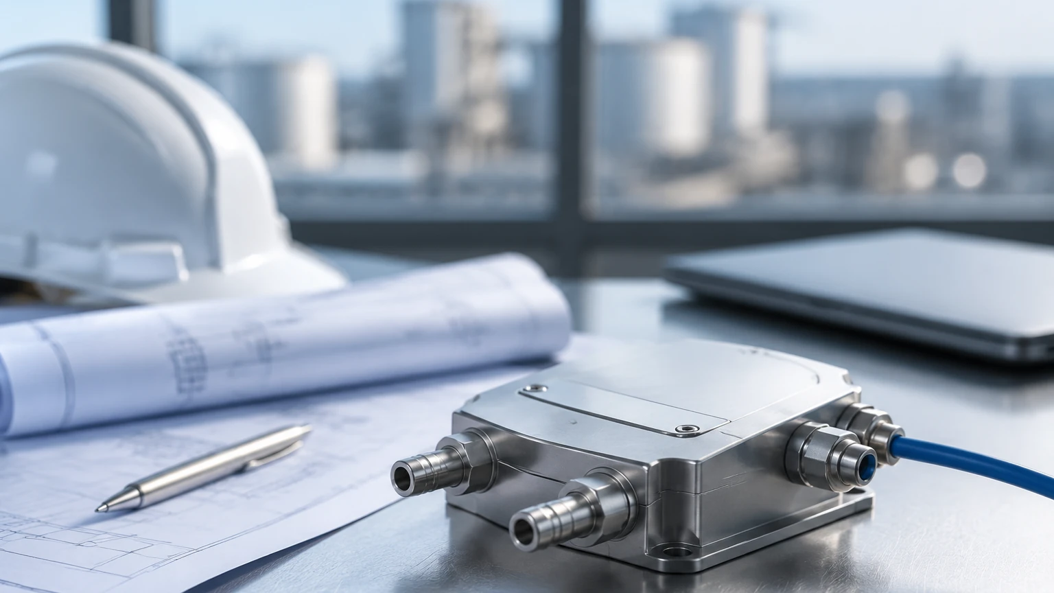
In the landscape of industrial process control, the difference pressure sensor—commonly referred to as a differential pressure (DP) transmitter—remains one of the most versatile and widely deployed instruments. While pressure measurement is a fundamental requirement in many systems, the ability to measure the "difference" between two points allows engineers to derive critical data regarding liquid level, flow rate, and filter health. For professionals in water treatment, chemical processing, and oil and gas, understanding the nuances of these sensors is essential for maintaining system integrity and accuracy.
Fundamental Principles of Difference Pressure Sensors
A difference pressure sensor operates by sensing two distinct pressures simultaneously. Unlike a gauge pressure sensor, which measures pressure relative to atmospheric pressure, or an absolute pressure sensor, which measures against a vacuum, the DP sensor calculates the delta between a High-Pressure (HP) side and a Low-Pressure (LP) side.
The Hydrostatic Head Principle
In level measurement applications, the sensor utilizes the principle of hydrostatic pressure. The pressure exerted by a liquid column is directly proportional to its height and its density. The formula used is:
P = ρ · g · h
Where:
* P is the hydrostatic pressure.
* ρ (rho) is the density of the liquid (kg/m³).
* g is the acceleration due to gravity (approximately 9.81 m/s²).
* h is the height of the liquid column (m).
In an open tank, the LP side of the difference pressure sensor is vented to the atmosphere, while the HP side is connected to the bottom of the tank. In a pressurized or closed vessel, the LP side is connected to the top of the tank to cancel out the effect of the internal gas pressure, ensuring that only the pressure exerted by the liquid height is measured.
Sensing Technologies
Most modern industrial sensors utilize one of two primary sensing elements:
1. Piezoresistive Sensors: These use a silicon diaphragm with integrated strain gauges. When pressure is applied, the diaphragm deforms, changing the electrical resistance. This change is converted into a standardized 4-20mA or digital signal.
2. Capacitive Sensors: These feature a sensing diaphragm positioned between two fixed capacitor plates. Pressure shifts the diaphragm, altering the capacitance. This method is often preferred for high-accuracy applications and provides excellent stability over time.
Key Selection Criteria for Industrial Applications
Selecting the correct difference pressure sensor requires a comprehensive evaluation of the process environment. Failure to account for chemical compatibility or pressure limits can lead to premature instrument failure or hazardous leaks.
1. Wetted Materials and Chemical Compatibility
The diaphragm is the most critical component as it is in direct contact with the process media. Standard sensors often use Stainless Steel 316L, but highly corrosive environments (such as those found in chemical processing) may require exotic materials like Hastelloy C, Monel, or Tantalum. For food and beverage or pharmaceutical applications, hygienic fittings and FDA-approved fill fluids (like glycerin or food-grade oil) are mandatory.
2. Pressure Range and Overpressure Protection
Engineers must define both the calibrated range (the specific DP range the sensor will measure) and the static pressure (the maximum pressure the vessel can reach). It is vital to ensure the sensor has sufficient overpressure protection; if a valve is opened incorrectly, one side of the sensor may experience the full process pressure while the other is at zero, which can damage a non-protected diaphragm.
3. Output and Communication Protocols
While the 4-20mA analog signal remains the industry standard, many modern facilities require digital integration. Common protocols include:
* HART: Allows for remote calibration and diagnostics over the existing 4-20mA loop.
* Modbus RTU: Ideal for integration into PLC systems in industrial automation.
* Foundation Fieldbus/Profibus: Used in large-scale plant architectures for high-speed data exchange.
Installation and Engineering Best Practices
The accuracy of a difference pressure sensor is heavily dependent on how it is installed. Improper piping or mounting can introduce errors that no amount of software calibration can fix.
Impulse Piping and Manifolds
Impulse lines are the small-bore pipes that carry the pressure from the process vessel to the sensor. To ensure reliable readings:
* Slope: Impulse lines should be sloped (at least 1:12) to allow gas bubbles to escape back into the tank (in liquid service) or condensate to drain (in gas service).
* Manifolds: A 3-way or 5-way valve manifold should be used. This allows the sensor to be isolated from the process for maintenance and enables "zeroing" the sensor by equalizing the pressure between the HP and LP sides.
Remote Seals (Diaphragm Seals)
In applications involving high-temperature fluids, viscous liquids that might clog impulse lines, or highly corrosive media, remote seals are used. These consist of a flexible diaphragm connected to the sensor via a capillary tube filled with a transmission fluid. This keeps the sensitive electronics away from harsh process conditions. When using remote seals, engineers must account for the "capillary effect," where temperature changes can cause the fill fluid to expand or contract, potentially shifting the zero point.
Comparison with Other Level Measurement Technologies
When evaluating a Main Page for level measurement solutions, it is helpful to compare DP sensors against alternative technologies like radar or ultrasonic sensors.
| Feature | Difference Pressure Sensor | Radar (Non-Contact) | Ultrasonic |
| :— | :— | :— | :— |
| Measurement Principle | Hydrostatic Pressure | Electromagnetic Waves | Sound Waves |
| Media Contact | Yes (Direct or Seal) | No | No |
| Accuracy | High (0.075% to 0.04%) | Very High (up to 1mm) | Moderate |
| Density Sensitivity | High (Requires constant density) | None | None |
| Foam/Vapor Impact | Minimal | Minimal (Frequency dependent) | Significant |
| Cost | Moderate | High | Low to Moderate |
| Installation | Requires tank penetration | Top-mounted | Top-mounted |
Limitations and Mitigation Strategies
Despite their reliability, difference pressure sensors have specific limitations that must be managed during the design phase.
* Density Variations: Since the sensor measures weight (pressure), any change in the liquid's density—often caused by temperature fluctuations—will result in an incorrect level reading. In critical applications, a temperature sensor is used alongside the DP sensor to provide real-time density compensation in the control system.
* Clogging and Sediment: In wastewater or slurry applications, sediment can build up in the HP port. Using a flush-mounted diaphragm or a remote seal with a large surface area can mitigate this risk.
* Gas Pockets in Impulse Lines: In liquid measurement, air trapped in the impulse lines creates a "cushion" that dampens the pressure signal. Regular bleeding of the lines or the use of automatic air vents is necessary for maintaining response speed.
Frequently Asked Questions (FAQs)
Q: Can a difference pressure sensor be used for flow measurement?
A: Yes. By placing a primary flow element (like an orifice plate or Venturi tube) in a pipe, the sensor measures the pressure drop across the restriction. The flow rate is proportional to the square root of the differential pressure.
Q: What is the difference between "wet leg" and "dry leg" installations?
A: In closed tank level measurement, if the gas above the liquid condenses, the LP impulse line will fill with liquid (a "wet leg"). This liquid column exerts its own pressure, which must be subtracted during calibration. If the gas does not condense, the line remains empty (a "dry leg").
Q: How often should a DP sensor be calibrated?
A: Most industrial-grade sensors have a stability specification (e.g., ±0.1% per 5-10 years). However, regulatory requirements or harsh process conditions often dictate annual or biennial calibration checks to ensure continued accuracy.
Q: Is it possible to measure the level of a vacuum tank with a DP sensor?
A: Yes. A difference pressure sensor is ideal for vacuum applications because the LP side compensates for the vacuum pressure, allowing the sensor to isolate the hydrostatic head of the liquid.
Summary of Confirmation for Project Stakeholders
Before finalizing the procurement of a difference pressure sensor, project engineers should confirm the following data points:
1. Specific Gravity: The minimum and maximum density of the process fluid across the operating temperature range.
2. Mounting Position: Whether the sensor will be mounted at the zero-level datum or if a "zero suppression" or "zero elevation" calculation is required.
3. Environmental Hazards: The need for explosion-proof (Ex d) or intrinsically safe (Ex i) certifications based on the facility's hazardous area classification.
4. Process Connection: The exact flange or thread size required to match existing tank nozzles.
By carefully considering these technical factors, industrial operators can leverage difference pressure sensors to achieve precise, repeatable, and cost-effective measurement across a vast array of process conditions. For more detailed technical specifications and product comparisons, professionals are encouraged to review product options and application support on the Main Page of specialized instrument manufacturers.