E and H Flow Meter
E and H Flow Meter
In the landscape of industrial process automation, the term "e and h flow meter" refers to the extensive range of flow measurement solutions provided by Endress+Hauser, a global leader in measurement instrumentation. For engineers and procurement specialists, selecting the correct flow meter is a critical decision that impacts plant efficiency, safety, and fiscal accountability. Whether managing water treatment facilities, chemical processing plants, or oil and gas refineries, understanding the underlying physics and application limits of these instruments is essential.
Flow measurement is rarely a one-size-fits-all solution. Different fluids—ranging from ultrapure water and corrosive chemicals to saturated steam and viscous crude oil—require specific sensing technologies. This guide explores the primary measurement principles utilized in high-end flow instrumentation, provides selection criteria, and outlines installation best practices to ensure long-term accuracy.
Core Measurement Principles
Before selecting an e and h flow meter, it is vital to understand the physical principles that govern different sensor types. Each technology interacts with the process media in a unique way, determining its suitability for specific industrial environments.
Electromagnetic Flow Measurement (Magmeters)
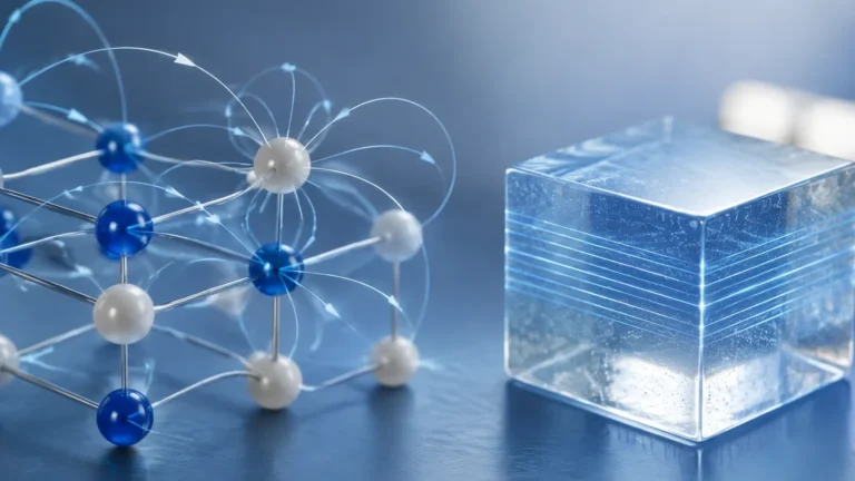
Electromagnetic flow meters operate based on Faraday’s Law of Induction. This principle states that a conductor (the fluid) moving through a magnetic field generates an electrical voltage. For this to work, the fluid must have a minimum electrical conductivity, typically ≥ 5 μS/cm.
* The Physics: As the liquid flows through the pipe, it passes through a magnetic field generated by coils. The resulting voltage, picked up by electrodes on the pipe wall, is directly proportional to the flow velocity.
* Applications: Ideal for water, wastewater, acids, and alkalis. Since there are no moving parts or obstructions in the flow profile, pressure loss is negligible.
Coriolis Mass Flow Measurement
Coriolis meters are often considered the "gold standard" because they measure mass flow directly rather than volume. This is crucial because mass remains constant regardless of changes in temperature or pressure.
* The Physics: The meter contains one or more oscillating tubes. As fluid flows through the vibrating tube, it induces a Coriolis force that causes the tube to twist. The degree of twist (phase shift) is proportional to the mass flow rate. Simultaneously, the oscillation frequency indicates the fluid's density.
* Applications: High-precision dosing, custody transfer of fuels, and complex chemical reactions where density and mass are critical variables.
Ultrasonic Flow Measurement
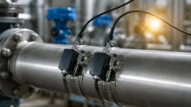
Ultrasonic meters use sound waves to determine flow velocity. They are available as inline versions or "clamp-on" sensors that attach to the outside of the pipe.
* The Physics (Transit-Time): Two transducers send ultrasonic pulses back and forth. A pulse traveling with the flow moves faster than one traveling against it. The time difference (Δt) is used to calculate velocity.
* Applications: Non-invasive measurement for retrofitting existing systems, or for measuring ultrapure fluids where contamination must be avoided.
Vortex Flow Measurement
Vortex meters rely on the Karman Vortex Street principle. When a fluid encounters a "shedder bar" in the meter body, it creates alternating vortices (swirls).
* The Physics: The frequency at which these vortices are shed is directly proportional to the flow velocity. A sensor (often a capacitive or piezoelectric element) detects these pressure fluctuations.
* Applications: Primarily used for steam (saturated and superheated), gases, and low-viscosity liquids.
Technical Selection Criteria
Choosing an e and h flow meter requires a detailed analysis of the process conditions. Engineers should refer to the following table to narrow down the technology based on media and performance requirements.
| Technology | Typical Accuracy | Media Type | Min. Conductivity | Pressure Loss |
| :— | :— | :— | :— | :— |
| Electromagnetic | ±0.2% to ±0.5% | Conductive Liquids | >5 μS/cm | Negligible |
| Coriolis | ±0.05% to ±0.1% | Liquids & Gases | N/A | Low to Medium |
| Ultrasonic | ±0.5% to ±2.0% | Clean Liquids | N/A | None (Clamp-on) |
| Vortex | ±0.75% to ±1.0% | Steam, Gas, Liquid | N/A | Medium |
| Thermal Mass | ±1.0% to ±5.0% | Clean Gases | N/A | Low |
Fluid Properties and Environmental Factors
1. Viscosity: High-viscosity fluids (like heavy oils) may require Coriolis meters, as vortex meters require a certain Reynolds number to function accurately.
2. Conductivity: If the fluid is non-conductive (e.g., demineralized water or hydrocarbons), electromagnetic meters cannot be used.
3. Temperature and Pressure: Standard industrial meters often handle up to 200°C (392°F) and 40 bar (580 psi). Extreme applications may require specialized high-temperature alloys or high-pressure housings rated for PN100 or higher.
4. Corrosion Resistance: The wetted parts (liners for magmeters, tubes for Coriolis) must be compatible with the media. Common materials include 316L Stainless Steel, Hastelloy, PFA, and PTFE.
Installation Considerations and Best Practices
Even the most advanced e and h flow meter will fail to provide accurate data if installed incorrectly. Proper mechanical and electrical integration is paramount.
Straight Pipe Runs (U/D Requirements)
Most flow meters require a stable flow profile to measure accurately. Turbulence caused by elbows, valves, or pumps can introduce significant errors.
* Upstream (U): Generally requires 5 to 10 times the pipe diameter (DN) of straight pipe.
* Downstream (D): Generally requires 2 to 5 times the pipe diameter (DN).
* Exception: Some modern electromagnetic meters with "zero-DN" technology can be installed immediately after an elbow without loss of accuracy, though this should be verified against the specific model's data sheet.
Orientation and Filling
For liquid applications, the pipe must always be completely full.
* Vertical Installation: Flowing upward is preferred, as this ensures the pipe remains full and air bubbles can escape.
* Horizontal Installation: The sensor electrodes in a magmeter should be positioned horizontally (3 o'clock and 9 o'clock positions) to prevent interference from sediment at the bottom or air pockets at the top.
Grounding and Shielding
Electromagnetic meters are particularly sensitive to stray electrical currents in the piping system. Proper grounding to the process fluid is required, often achieved via grounding rings or grounding electrodes, especially when using plastic or lined pipes.
Limitations and Common Risks
While industrial flow meters are robust, they are not infallible. Awareness of common failure points can prevent costly downtime.
* Entrained Air: In liquid flow, air bubbles can cause significant measurement drift or complete signal loss in ultrasonic and electromagnetic meters. In Coriolis meters, "two-phase flow" can lead to measurement errors if the meter is not specifically designed with advanced signal processing for entrained gas.
* Scaling and Coating: In wastewater or chemical dosing, build-up on the electrodes or the inner wall of the meter can insulate the sensor, leading to inaccurate readings. Regular cleaning or the use of meters with "electrode cleaning" functions may be necessary.
* Vibration: Coriolis and Vortex meters are sensitive to external mechanical vibrations. If installed near heavy machinery or reciprocating pumps, specialized damping mounts or flexible connectors may be required.
Integration with Level Measurement Systems
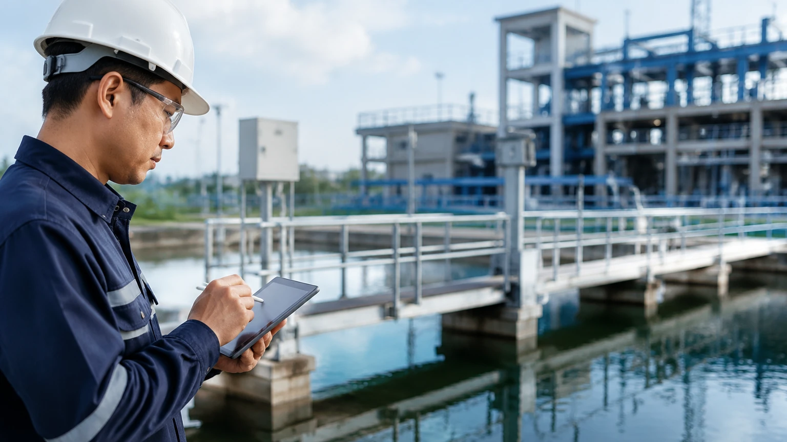
In many B2B industrial applications, flow measurement is used in conjunction with level measurement to provide a complete picture of process inventory. For instance, in a chemical storage tank, a radar level meter provides the static volume, while an e and h flow meter monitors the dynamic inflow and outflow.
Manufacturers like Welk provide a variety of level measurement instruments that complement flow systems. For those looking to optimize their entire process loop, it is often beneficial to Review product options and application support to ensure that level and flow sensors are calibrated to work in tandem, providing redundant data for safety-critical applications.
Frequently Asked Questions (FAQ)
Q: Can I use an electromagnetic flow meter for oil?
No. Most oils are non-conductive. For hydrocarbons, a Coriolis or Ultrasonic meter is generally recommended.
Q: What is the difference between a "Full Bore" and "Insertion" meter?
Full bore meters measure the entire flow stream and are more accurate. Insertion meters only measure a single point in the flow profile and are typically used for very large pipe diameters where a full-bore meter would be cost-prohibitive.
Q: How often should a flow meter be calibrated?
This depends on the industry and the criticality of the measurement. In regulated industries like pharmaceuticals or food production, annual calibration is common. In general water treatment, a check every 2-3 years may suffice unless a shift in accuracy is detected.
Q: What is the "Turndown Ratio"?
It is the ratio between the maximum and minimum flow rate that a meter can measure accurately. For example, a 100:1 turndown ratio means a meter rated for 1000 L/min can accurately measure down to 10 L/min.
Conclusion
Selecting an e and h flow meter involves balancing precision requirements with the realities of the process environment. By understanding the physics of the measurement—whether it be the electromagnetic induction of a magmeter or the oscillation of a Coriolis tube—engineers can select a tool that provides reliable data for years. When combined with robust level measurement technologies, these instruments form the backbone of modern industrial automation, ensuring that resources are managed efficiently and safely. For further technical specifications on level and flow integration, visiting the Main Page of specialized instrument providers can offer deeper insights into customized OEM/ODM solutions.