Electromagnetic Flow Meter Electronics
Electromagnetic Flow Meter Electronics
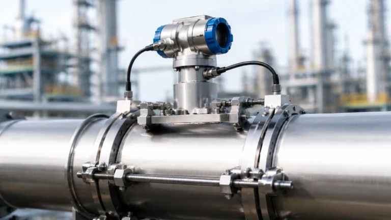
In the landscape of industrial process control, the electromagnetic flow meter (magmeter) is a cornerstone technology for measuring the flow of conductive liquids. While the physical sensor—consisting of the flow tube, liners, and electrodes—interacts directly with the medium, the electromagnetic flow meter electronics (often referred to as the converter or transmitter) serve as the "brain" of the system. These electronic components are responsible for generating the magnetic field, capturing minute voltage signals, and translating them into actionable data for industrial automation systems.
Selecting the right electronics is as critical as choosing the sensor material. High-performance electronics ensure long-term stability, noise rejection, and seamless integration into modern control architectures. This guide provides a technical overview of the principles, components, and selection criteria for electromagnetic flow meter electronics to assist engineers in making informed procurement decisions.
Understanding the Role of Electronics in Electromagnetic Flow Measurement
Electromagnetic flow meter electronics perform three primary functions: excitation, signal processing, and communication. Unlike mechanical flow meters that rely on moving parts, a magmeter uses an electromagnetic field to induce a voltage in the flowing liquid. The electronics must control this field with extreme precision.
Modern electronics have evolved from simple analog transmitters to sophisticated digital signal processors (DSP). These advancements allow for features such as empty pipe detection, self-diagnostics, and multi-parameter measurement (e.g., forward and reverse flow). For organizations seeking comprehensive industrial measurement solutions, reviewing the Main Page of a professional manufacturer like Welk provides insight into how these electronic systems are integrated into broader instrumentation portfolios.
Measurement Principles: From Faraday’s Law to Digital Signal Processing
The operation of electromagnetic flow meter electronics is based on Faraday’s Law of Electromagnetic Induction. The law states that a conductor moving through a magnetic field will produce an electrical voltage proportional to its velocity.
The Mathematical Foundation
The relationship is expressed by the formula:
E = B × v × D
Where:
* E is the induced voltage (the signal measured by the electronics).
* B is the magnetic field strength (generated by the electronics via coils).
* v is the average velocity of the liquid.
* D is the diameter of the pipe (the distance between the electrodes).
Excitation Methods
The electronics supply current to the coils to create the magnetic field. There are two primary excitation methods used in industrial electronics:
1. High-Frequency AC Excitation: Historically used to overcome electrochemical noise, though it can suffer from zero-point drift and high power consumption.
2. Low-Frequency Pulsed DC Excitation: The industry standard for modern electronics. By switching the polarity of the DC field at a low frequency (typically 1/16 to 1/2 of the mains frequency), the electronics can effectively cancel out noise and electrochemical interference, ensuring a stable zero point.
Core Components of Electromagnetic Flow Meter Electronics
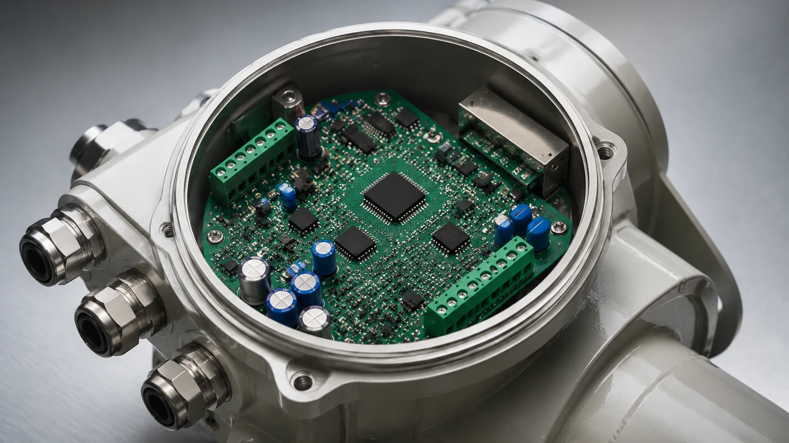
The internal architecture of electromagnetic flow meter electronics is designed to handle extremely low-level signals, often in the microvolt (µV) range, in environments filled with industrial electrical noise.
1. The Excitation Circuit
This circuit regulates the current sent to the sensor coils. Advanced electronics use constant-current excitation to ensure the magnetic field remains stable even if the coil resistance changes due to temperature fluctuations.
2. Signal Preamplifier and A/D Converter
The induced voltage at the electrodes is very weak and has high impedance. The electronics utilize a high-input-impedance preamplifier to boost the signal without distorting it. Following amplification, a high-resolution Analog-to-Digital (A/D) converter (typically 16-bit or 24-bit) transforms the signal into digital data for processing.
3. Microcontroller Unit (MCU)
The MCU is the core processing engine. It performs complex algorithms for digital filtering, flow calculation, and error correction. It also manages the user interface (LCD display) and handles diagnostic routines, such as checking for electrode scaling or coil short-circuits.
4. Output and Communication Modules
To interact with a Distributed Control System (DCS) or Programmable Logic Controller (PLC), the electronics convert the calculated flow rate into standard signals. Common outputs include:
* 4-20mA Analog: The standard for most industrial loops.
* Pulse/Frequency: Used for totalizing flow.
* Digital Protocols: RS485 (Modbus), HART, Profibus, or Foundation Fieldbus.
Technical Selection Criteria for Industrial Applications
When evaluating electromagnetic flow meter electronics, engineers must balance technical performance with environmental constraints. The following table summarizes the key considerations for different electronic configurations.
Selection Comparison Table
| Feature | Integral Converter | Remote (Split) Converter |
| :— | :— | :— |
| Installation | Electronics mounted directly on the sensor. | Electronics mounted on a wall or panel via cable. |
| Max Temperature | Limited by electronic component tolerance (typically < 60°C). | Allows sensor to operate in high-temp fluids (> 150°C). |
| Accessibility | Best for accessible pipes at ground level. | Ideal for buried pipes or high-altitude installations. |
| Vibration Resistance | Sensitive to heavy pipe vibration. | High; electronics are isolated from vibration. |
| Cable Requirements | None; internal wiring only. | Requires specialized shielded signal and excitation cables. |
| Typical Protection | IP65 / IP67 | IP65 (Converter) / IP68 (Sensor) |
Power Supply Options
Electronics are typically available in three power configurations:
* AC Power (85-265V AC): Standard for plant-wide installations where mains power is available.
* DC Power (18-36V DC): Preferred for integration into 24V control cabinets.
* Battery Powered: Essential for remote water distribution networks where no external power exists. These electronics use ultra-low-power microprocessors to provide years of service on a single battery pack.
Installation Guidelines for Optimizing Electronic Performance
The reliability of electromagnetic flow meter electronics depends heavily on proper installation, particularly regarding grounding and signal integrity.
Grounding Requirements
Because the electronics measure microvolt signals, they are highly susceptible to stray currents in the piping system. The liquid, the sensor, and the electronics must be at the same electrical potential.
* Conductive Pipes: The sensor and electronics should be bonded to the metal pipe flanges.
* Non-Conductive/Lined Pipes: Grounding rings must be installed to provide a contact point with the fluid, ensuring the electronics have a stable reference ground.
Cable Shielding and Separation
For remote-type electronics, the signal cable between the sensor and the converter is the most vulnerable part of the system.
* Shielding: Use double-shielded cables to prevent electromagnetic interference (EMI).
* Separation: Never run flow meter signal cables in the same conduit or tray as high-voltage power lines or variable frequency drive (VFD) cables. A minimum separation of 500 mm (approx. 20 inches) is recommended.
Environmental Protection
Electronics should be shielded from direct sunlight to prevent overheating and UV degradation of the display. In humid or tropical environments, using electronics with potted (encapsulated) circuit boards prevents moisture ingress and corrosion.
Limitations and Environmental Constraints
While electromagnetic flow meter electronics are highly versatile, they have specific functional boundaries:
1. Minimum Conductivity: The electronics cannot process signals from liquids with conductivity lower than 5 μS/cm (microsiemens per centimeter). This excludes demineralized water, oils, and gases.
2. Partially Filled Pipes: Standard electronics assume a full pipe for flow calculation. If the pipe is partially empty, the cross-sectional area calculation is incorrect, leading to significant errors. For these applications, specialized electronics with extra electrodes for level detection are required.
3. Signal Interference: Large motors or transformers located near the electronics can induce noise that the DSP may struggle to filter, leading to "jitter" in the flow reading.
Frequently Asked Questions (FAQs)
Q: Can the electronics be upgraded without replacing the flow sensor?
A: In many cases, yes. If the excitation requirements and K-factor (calibration constant) of the sensor are known, modern electronics can often be calibrated to work with older sensors, provided the coil resistance is compatible.
Q: What does the "Empty Pipe Alarm" actually measure?
A: The electronics monitor the impedance between the electrodes. When the pipe is empty, the impedance increases dramatically. The electronics detect this change and can be programmed to drive the 4-20mA output to a specific fail-safe value (e.g., 0mA or 22mA).
Q: How often should the electronics be calibrated?
A: While the sensor itself is stable, the electronic components can drift over time. Most industrial standards recommend a verification of the electronics every 1 to 2 years using a signal simulator that mimics the sensor's output.
Q: Is it possible to use one set of electronics for two different sensors?
A: Generally, no. Each set of electronics is matched to the specific K-factor and diameter of a single sensor during factory calibration to ensure the stated accuracy (typically ±0.5% or ±0.2%).
Conclusion
Electromagnetic flow meter electronics are the critical link between a physical process and a digital control system. By understanding the principles of pulsed DC excitation, the importance of proper grounding, and the trade-offs between integral and remote configurations, engineers can ensure high accuracy and long-term reliability in their flow measurement applications. For technical specifications on high-quality measurement instruments and to explore a full range of industrial sensors, users should consult the Main Page for detailed product data and application support.