Electromagnetic Flow
Electromagnetic Flow
Electromagnetic flow measurement, commonly referred to as magmeter technology, represents one of the most versatile and accurate methods for monitoring the volumetric flow rate of conductive liquids within industrial processes. Unlike mechanical flow meters that rely on moving parts, electromagnetic flow meters utilize the principles of physics to derive flow data without obstructing the fluid path. This characteristic makes them indispensable in sectors ranging from municipal water treatment to aggressive chemical processing.
In the context of industrial automation, flow and level measurement often work in tandem to provide a complete picture of process efficiency. While manufacturers like Welk provide specialized solutions for level monitoring—including radar and ultrasonic sensors—the integration of electromagnetic flow data is critical for mass balance, leak detection, and precise dosing. Understanding the underlying principles, selection criteria, and installation nuances of electromagnetic flow technology is essential for any engineering team tasked with optimizing fluid systems.
Measurement Principles: Faraday’s Law of Induction
The operation of an electromagnetic flow meter is based on Faraday’s Law of Electromagnetic Induction, formulated by Michael Faraday in 1831. The law states that a voltage is induced when a conductor moves through a magnetic field. In the case of a magmeter, the "conductor" is the process liquid itself.
The Fundamental Equation
The relationship between the induced voltage and the fluid velocity is expressed by the following equation:
E = B × v × D
* E (Induced Voltage): The electrical potential generated across the electrodes.
* B (Magnetic Field Strength): The intensity of the magnetic field generated by the meter’s coils.
* v (Mean Velocity): The average speed of the liquid moving through the pipe.
* D (Conductor Length/Pipe Diameter): The distance between the sensing electrodes, which corresponds to the internal diameter of the meter.
How the Process Works
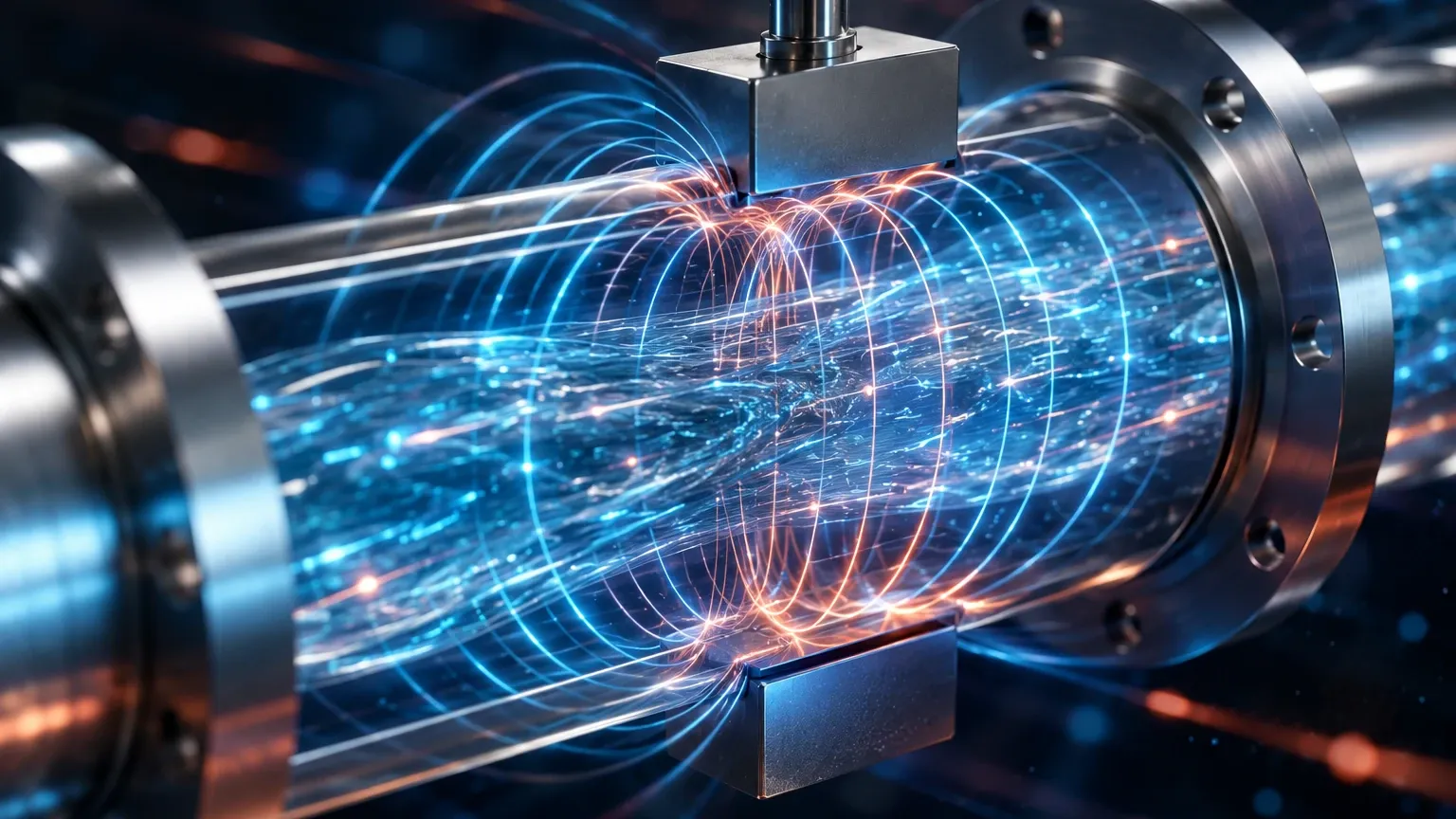
Inside the flow meter body, two electromagnetic coils are positioned opposite each other to generate a constant magnetic field perpendicular to the flow direction. As a conductive liquid (such as water, acids, or slurries) flows through this field, it generates a voltage. Two electrodes, mounted flush with the pipe wall, detect this voltage and transmit the signal to a converter. Since the magnetic field strength (B) and the pipe diameter (D) are fixed constants, the induced voltage (E) is directly proportional to the fluid velocity (v). The transmitter then calculates the volumetric flow rate based on the cross-sectional area of the pipe.
Key Components and Material Selection
Selecting the correct materials for an electromagnetic flow meter is critical for ensuring long-term reliability and accuracy. Because the meter is in direct contact with the process medium, the liner and electrodes must be compatible with the fluid's chemical and physical properties.
1. Liner Materials
The liner insulates the metal meter body from the conductive fluid and the induced voltage. Common materials include:
* PTFE (Teflon): Excellent for high temperatures and highly corrosive chemicals. However, it is susceptible to mechanical damage from abrasive slurries.
* PFA: Similar to PTFE but offers better vacuum resistance and smoother surfaces for hygienic applications.
* Hard Rubber / Ebonite: Often used in water treatment and for fluids with low concentrations of solids.
* Polyurethane: Highly resistant to abrasion, making it the standard choice for mining slurries and wastewater containing sand or grit.
2. Electrode Materials
Electrodes must be conductive and resistant to corrosion. Selection typically includes:
* Stainless Steel (316L): The standard for water and mildly corrosive liquids.
* Hastelloy C: Used for more aggressive chemical environments where stainless steel would fail.
* Tantalum: Reserved for highly acidic processes, such as hydrochloric or sulfuric acid.
* Platinum/Iridium: Used in specialized chemical or food-grade applications requiring maximum inertness.
Selection Table: Liner and Electrode Compatibility
| Application | Recommended Liner | Recommended Electrode | Temperature Limit |
| :— | :— | :— | :— |
| Potable Water | Hard Rubber / PFA | SS316L | 80°C |
| Municipal Sewage | Polyurethane | SS316L | 60°C |
| Concentrated Acids | PTFE / PFA | Tantalum / Hastelloy | 150°C |
| Mining Slurries | Polyurethane | Hastelloy C | 60°C |
| Food & Beverage | PFA (FDA approved) | SS316L / Platinum | 130°C |
Practical Selection Criteria
When evaluating electromagnetic flow technology for a project, several technical factors must be confirmed to ensure the device performs within its specified accuracy (typically ±0.5% of rate or better).
Conductivity Requirements
The most significant limitation of electromagnetic flow meters is that the fluid must be electrically conductive. Most industrial magmeters require a minimum conductivity of 5 μS/cm (microsiemens per centimeter). This makes them unsuitable for hydrocarbons (oils, fuels), distilled water, or gases.
Flow Velocity Range
Magmeters are most accurate when the fluid velocity is between 0.5 m/s and 10 m/s. If the pipe is oversized and the velocity is too low (below 0.3 m/s), the signal-to-noise ratio decreases, leading to inaccuracies. Conversely, velocities exceeding 10 m/s can cause excessive liner wear and pressure drops.
Pressure and Temperature
While the electromagnetic principle is independent of pressure, the physical construction of the meter (flanges and liners) has strict limits. High-pressure applications require specialized flange ratings (e.g., ANSI 300 or 600), while high-temperature applications may require remote-mounted electronics to protect the transmitter from heat.
For engineers managing complex tank farms or chemical processing plants, coordinating flow data with level data is vital. While Welk offers a robust range of level measurement instruments, including radar and ultrasonic transmitters, the Main Page provides further insights into how these technologies integrate into broader industrial automation frameworks.
Installation Considerations
Proper installation is the single most important factor in achieving the rated accuracy of an electromagnetic flow meter. Because the meter relies on a stable velocity profile, turbulence must be minimized.
1. Straight Pipe Runs
To ensure a fully developed laminar flow profile, the meter should be installed with a specific amount of straight pipe upstream and downstream. The general rule is:
* Upstream: 5 times the nominal pipe diameter (5D).
* Downstream: 3 times the nominal pipe diameter (3D).
If there are high-turbulence sources like pumps or modulating valves nearby, the upstream requirement may increase to 10D or more.
2. Pipe Orientation and Filling
The meter must always be completely full of liquid. If air pockets form or if the pipe is only partially full, the meter will provide erratic readings or fail entirely.
* Vertical Installation: The preferred orientation is vertical with the flow moving upward. This ensures the pipe remains full and prevents the accumulation of air bubbles.
* Horizontal Installation: If installed horizontally, the electrode axis must be horizontal (not vertical) to prevent air bubbles at the top or sediment at the bottom from interfering with the electrode signal.
3. Grounding
Since the induced voltage signal is often in the millivolt range, electrical noise can easily distort the measurement. Proper grounding is mandatory. If the pipe is unlined metal, the meter can be grounded directly to the pipe. If the pipe is plastic or lined, grounding rings must be installed to provide an electrical path to the fluid.
Limitations and Common Risks
While highly reliable, electromagnetic flow meters are not a "one-size-fits-all" solution. Engineers should be aware of the following risks:
* Non-Conductive Fluids: As mentioned, they cannot measure oils, steam, or gases. For these applications, vortex or ultrasonic (transit-time) meters are preferred.
* Liner Vacuum Collapse: In systems where a vacuum may occur (e.g., rapid cooling of a steam-cleaned line), certain liners like PTFE may collapse or peel away from the tube wall. PFA or reinforced liners should be specified for vacuum service.
* Coating and Scaling: If the fluid is prone to leaving deposits (like calcium carbonate or heavy oils), the electrodes can become insulated. Some modern magmeters include electrode cleaning circuits or removable electrodes to mitigate this.
* Magnetic Interference: High-power cables or large motors located in close proximity to the meter can create electromagnetic interference (EMI) that disrupts the magnetic field of the sensor.
Frequently Asked Questions (FAQ)
Q: Can a magmeter measure flow in both directions?
A: Yes, most modern electromagnetic flow meters are bi-directional. They can be configured to measure flow in both forward and reverse directions, which is useful for loading/unloading applications.
Q: Does the viscosity of the fluid affect accuracy?
A: Generally, no. One of the primary advantages of electromagnetic flow technology is that it is independent of viscosity, density, and pressure, provided the flow remains laminar or predictably turbulent and the fluid is conductive.
Q: How often does an electromagnetic flow meter need calibration?
A: In stable applications like clean water, a magmeter can maintain accuracy for many years without recalibration. However, in abrasive or corrosive environments, annual verification is recommended to check for liner wear or electrode degradation.
Q: What happens if the fluid contains air bubbles?
A: Air bubbles are non-conductive. If they pass over the electrodes, they cause "noise" in the signal. If the volume of air is significant, the meter will over-read because it measures the velocity of the air-liquid mixture but assumes the pipe is full of liquid.
Conclusion: Integrating Flow and Level Solutions
Electromagnetic flow measurement is a cornerstone of modern process engineering, offering a combination of high accuracy, low maintenance, and wide chemical compatibility. By eliminating moving parts and providing an unobstructed flow path, magmeters reduce the total cost of ownership compared to mechanical alternatives.
For a comprehensive approach to process monitoring, flow data should be cross-referenced with level measurement. Whether you are monitoring the inflow to a storage tank or the discharge from a chemical reactor, the synergy between these two variables is key to operational safety and efficiency. For technical specifications on level measurement instruments that complement your flow systems, visit the Main Page to explore professional-grade radar, ultrasonic, and hydrostatic solutions.