Fci Thermal Mass Flow Meter
Fci Thermal Mass Flow Meter
In the landscape of industrial process control, the accurate measurement of gas flow is essential for energy management, environmental compliance, and process efficiency. Among the various technologies available, the thermal mass flow meter—specifically those developed by industry leaders like Fluid Components International (FCI)—stands out for its ability to provide direct mass flow measurement without the need for additional pressure or temperature compensation.
This guide explores the technical principles, selection criteria, and practical application of thermal dispersion technology, providing engineers with the necessary framework to evaluate the fci thermal mass flow meter within their specific operational contexts. While flow measurement is a distinct discipline, it often works in tandem with level measurement technologies, such as those found on the Main Page of industrial instrumentation providers, to ensure comprehensive vessel and process monitoring.
Measurement Principles: Thermal Dispersion Technology
The fundamental operating principle of a thermal mass flow meter is based on the laws of thermodynamics and the cooling effect of a moving fluid. Most high-performance instruments, including the fci thermal mass flow meter line, utilize the "thermal dispersion" method.
The Sensor Configuration
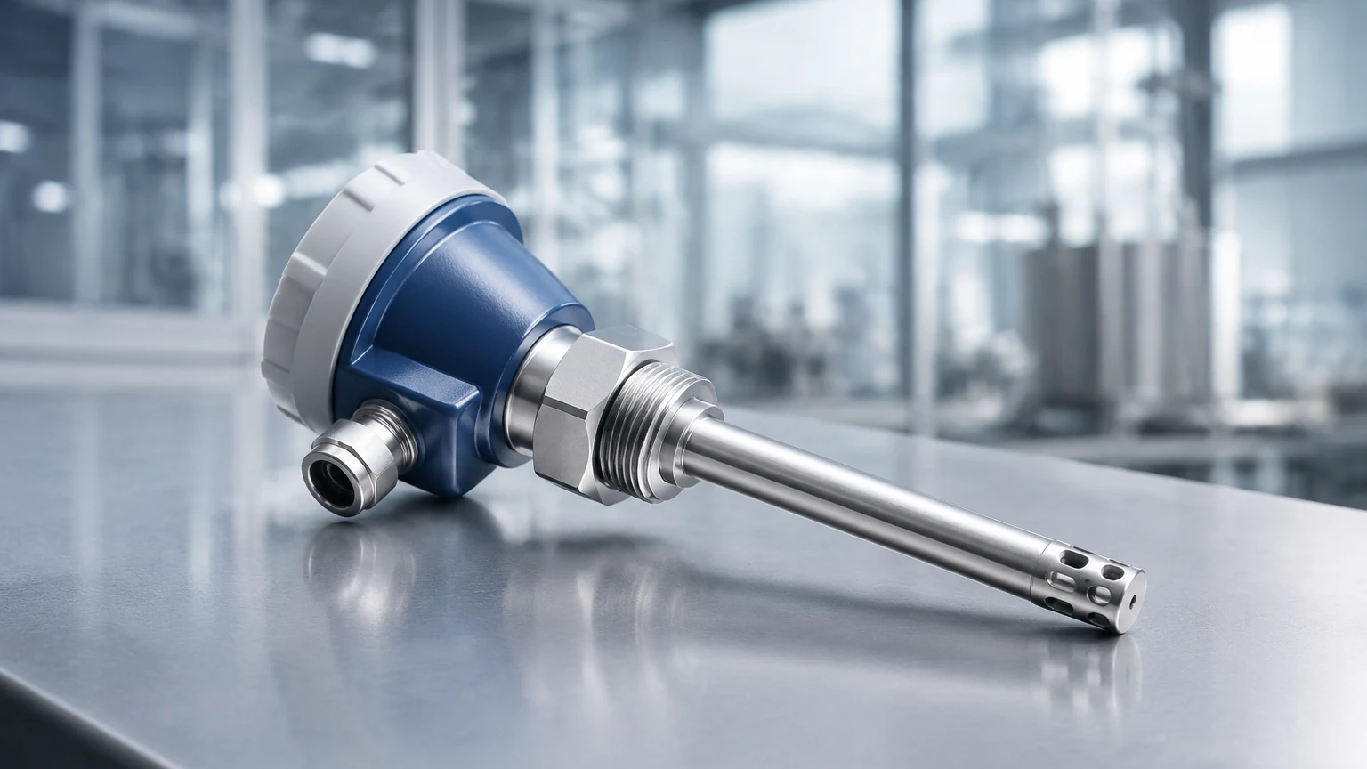
At the core of the device are two thermowell-protected Resistance Temperature Detectors (RTDs). These sensors are typically constructed from platinum and are immersed directly into the gas stream.
1. The Reference Sensor: This RTD measures the actual temperature of the process gas. It provides a baseline for the electronics to understand the fluid's ambient thermal state.
2. The Active (Heated) Sensor: This RTD is heated to a specific temperature above the reference sensor.
Constant Temperature Differential vs. Constant Power
There are two primary methods of controlling these sensors:
* Constant Temperature Differential: The electronics maintain a fixed temperature difference (ΔT) between the heated sensor and the reference sensor. As gas flows past the heated sensor, it carries away heat. To maintain the constant ΔT, the instrument must increase the power supplied to the heated sensor. This electrical power is directly proportional to the mass flow rate of the gas.
* Constant Power: The instrument provides a fixed amount of power to the heated sensor. As the flow rate increases, the temperature difference between the two sensors decreases. The measured ΔT is inversely proportional to the mass flow rate.
Because gas density changes with pressure and temperature, volumetric flow meters (like vortex or turbine meters) require external sensors and a flow computer to calculate mass. Thermal mass flow meters, however, respond to the heat-conducting properties of the gas molecules themselves, providing a direct mass flow reading in units such as kilograms per hour (kg/h) or Normal cubic meters per hour (Nm³/h).
Key Features of FCI Thermal Mass Flow Meters
FCI has pioneered several advancements in thermal dispersion technology that address common industrial challenges. Their designs are characterized by a lack of moving parts, which significantly reduces maintenance requirements and eliminates the risk of mechanical failure or pressure drops associated with intrusive elements like orifice plates.
Wide Turndown Ratio
One of the most significant advantages of this technology is its high turndown ratio, often exceeding 100:1. This allows the meter to accurately measure both extremely low flow rates (leak detection) and high-velocity process flows within the same instrument configuration.
Robust Construction
Industrial environments often involve corrosive gases or high-pressure steam cleaning. Thermal sensors are typically encased in Hastelloy-C or 316L stainless steel, ensuring longevity in harsh chemical or offshore environments. Unlike level measurement devices like ultrasonic sensors that might be affected by foam, thermal flow meters are primarily sensitive to the thermal conductivity and moisture content of the gas.
Selection Criteria and Technology Comparison
When selecting a flow meter, engineers must weigh the benefits of thermal dispersion against other common technologies. The following table provides a comparison based on typical industrial requirements.
Table 1: Flow Meter Technology Comparison
| Feature | Thermal Mass Flow Meter | Vortex Flow Meter | Differential Pressure (DP) | Ultrasonic (Transit-Time) |
| :— | :— | :— | :— | :— |
| Primary Measurement | Direct Mass Flow | Volumetric Flow | Volumetric/Velocity | Velocity |
| Moving Parts | None | None | None | None |
| Pressure Drop | Negligible | Moderate | High | None (In-line) |
| Low Flow Sensitivity | Excellent | Poor | Poor | Moderate |
| Gases Only? | Primarily (Gases/Air) | Liquids/Gases/Steam | Liquids/Gases/Steam | Liquids/Gases |
| Turndown Ratio | 100:1+ | 20:1 | 5:1 | 40:1 |
| Installation Cost | Moderate | Moderate | High (Manifolds/Piping) | High |
Practical Installation Considerations
To achieve the specified accuracy (typically ±1% of reading), the fci thermal mass flow meter requires a fully developed flow profile. This means the gas velocity must be uniform across the pipe's cross-section.
Straight Run Requirements
Disturbances such as elbows, valves, and reducers create turbulence that can bias the reading.
* Upstream: A minimum of 20 pipe diameters (D) of straight, unobstructed pipe is generally recommended.
* Downstream: A minimum of 5 pipe diameters (D) is required.
If these straight runs are not available, flow conditioners (vane-type or perforated plates) must be installed to stabilize the flow profile before it reaches the sensors.
Orientation and Immersion
For insertion-style meters, the sensor must be positioned precisely in the center of the pipe (the point of maximum velocity). In horizontal pipes, it is often recommended to install the meter at the 10 o'clock or 2 o'clock position to avoid moisture accumulation at the bottom of the pipe or air pockets at the top, although this is more critical for liquid applications than for dry gases.
Limitations and Common Risks
While highly versatile, thermal mass flow meters have specific limitations that must be managed:
1. Gas Composition Changes: Thermal dispersion is dependent on the specific heat and thermal conductivity of the gas. If the gas composition changes (e.g., a shift in the methane/CO2 ratio in biogas), the meter will require recalibration or a multi-gas calibration factor to maintain accuracy.
2. Moisture and Condensation: If water droplets hit the heated sensor, they cause a rapid cooling effect that the meter interprets as a massive spike in flow. In applications with high humidity or saturated gas, heated sensor tips or moisture separators are necessary.
3. Coating and Fouling: While the sensors are robust, a thick buildup of grease, paraffin, or dust can insulate the sensor, leading to a sluggish response and measurement errors. Regular inspection is recommended in "dirty" gas applications.
Integration with Level Measurement Systems
In many B2B industrial applications, such as chemical processing or water treatment, flow and level measurement are used in tandem. For instance, in a wastewater treatment plant, thermal mass flow meters monitor the aeration air delivered to tanks, while ultrasonic or radar level meters monitor the basin levels.
Welk provides a range of level measurement solutions, including radar level meters and hydrostatic transmitters, which are essential for maintaining the mass balance of a system. When engineers evaluate an fci thermal mass flow meter for gas delivery, they often simultaneously review their tank inventory systems. For a comprehensive look at how these instruments integrate into a complete process automation strategy, you may Review product options and application support on our Main Page.
Frequently Asked Questions (FAQ)
Q: Can a thermal mass flow meter be used for steam?
A: Generally, no. Thermal mass flow meters are not suitable for steam because the phase change (condensation) on the sensor tip causes significant measurement errors. Vortex or DP meters are preferred for steam applications.
Q: Does the fci thermal mass flow meter require periodic recalibration?
A: In clean gas applications like compressed air, the calibration is very stable. However, in regulated industries or applications involving corrosive gases, annual or biennial calibration is recommended to ensure compliance and accuracy.
Q: How does the meter handle changing pressures?
A: Because it measures mass flow, changes in pressure do not affect the reading (within the instrument's rated pressure range). As pressure increases, the gas becomes denser, and more molecules carry heat away from the sensor, which the meter correctly interprets as increased mass flow.
Q: What is the difference between an insertion meter and an in-line meter?
A: Insertion meters are designed for large pipes (typically >50mm) and are installed through a flange or NPT fitting. In-line meters include a calibrated flow body and are used for smaller pipes to ensure the highest possible accuracy by controlling the flow profile within the device itself.
Conclusion
The fci thermal mass flow meter remains a standard-bearer for gas flow measurement due to its reliability and direct mass flow capabilities. By understanding the thermal dispersion principle and adhering to strict installation guidelines regarding straight runs and gas composition, engineers can achieve highly accurate data for process optimization. When combined with advanced level measurement technologies, these instruments provide the data foundation necessary for modern industrial automation and efficient resource management.