Fluid Flow Meter
Fluid Flow Meter
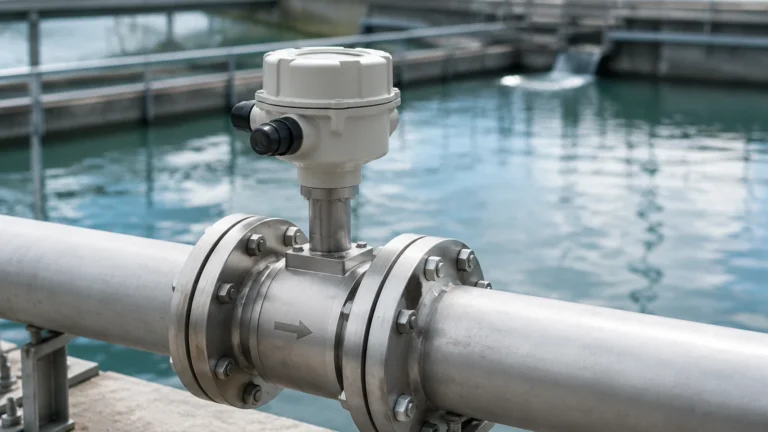
In the realm of industrial process control, the accurate measurement of fluid movement is as critical as monitoring the contents of a storage vessel. A fluid flow meter is an instrument used to measure the linear, nonlinear, mass, or volumetric flow rate of a liquid or a gas. For engineers and plant managers, selecting the correct flow meter is a complex task that requires a deep understanding of fluid dynamics, installation constraints, and the specific requirements of the application, whether it be water treatment, chemical processing, or oil and gas production.
While level measurement instruments—such as those found on the Main Page—provide data on the quantity of material in a tank, flow meters provide the dynamic data of how that material moves through the system. Together, these instruments form the backbone of industrial automation and inventory management.
Measurement Principles and Technologies
Before selecting a fluid flow meter, it is essential to understand the physical principles that govern different measurement technologies. Each method has specific strengths and is suited to different fluid characteristics.
Electromagnetic Flow Meters (Magmeters)
Electromagnetic flow meters operate based on Faraday’s Law of Electromagnetic Induction. This law states that a conductor moving through a magnetic field produces an electrical signal. In this application, the fluid acts as the conductor. As the conductive liquid flows through a magnetic field generated by the meter, it creates a voltage proportional to the velocity of the flow.
* Requirement: The fluid must be electrically conductive (typically >5 μS/cm).
* Advantage: No moving parts and no pressure drop.
Ultrasonic Flow Meters
Ultrasonic meters use sound waves to determine the velocity of a fluid. There are two primary types:
1. Transit-Time: These meters send ultrasonic pulses back and forth across the pipe. The difference in time it takes for the pulse to travel with the flow versus against the flow is proportional to the fluid velocity. These are best for clean liquids.
2. Doppler: These meters reflect sound waves off particles or bubbles in the fluid. The frequency shift (Doppler effect) of the reflected signal indicates the flow speed. These are ideal for slurries or aerated liquids.
Vortex Flow Meters
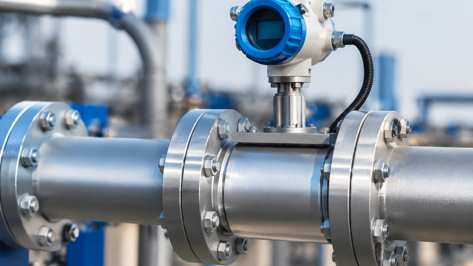
Vortex meters utilize the principle of Karman vortex shedding. An obstruction (bluff body) is placed in the flow path, creating alternating vortices downstream. The frequency at which these vortices are shed is directly proportional to the velocity of the fluid. This technology is highly versatile, capable of measuring liquids, gases, and steam.
Turbine Flow Meters
Turbine meters consist of a multi-bladed rotor mounted in a pipe, perpendicular to the fluid flow. As the fluid passes through the blades, it causes the rotor to spin at a speed proportional to the flow rate. The rotation is sensed magnetically or mechanically to provide a flow reading. These are highly accurate for clean, low-viscosity fluids.
Differential Pressure (DP) Flow Meters
DP meters calculate flow by measuring the pressure drop across a restriction in the pipe, such as an orifice plate or a Venturi tube. According to Bernoulli’s equation, the square root of the pressure drop is proportional to the flow rate. While traditional, they remain a staple in high-pressure and high-temperature steam applications.
Practical Selection Criteria
Choosing the right fluid flow meter requires a systematic evaluation of the process conditions. The following table provides a comparison of common technologies used in industrial automation.
Flow Meter Comparison Table
| Technology | Suitable Fluids | Typical Accuracy | Pressure Drop | Relative Cost |
| :— | :— | :— | :— | :— |
| Electromagnetic | Conductive Liquids | ±0.5% | None | Medium |
| Ultrasonic | Clean/Dirty Liquids | ±1.0% | None | High |
| Vortex | Liquid, Gas, Steam | ±1.0% | Low | Medium |
| Turbine | Clean, Low Viscosity | ±0.25% | High | Medium |
| Differential Pressure | Liquid, Gas, Steam | ±1.0% to 2.0% | High | Low to Medium |
| Coriolis (Mass) | Most Fluids | ±0.1% | Medium | Very High |
Key Evaluation Factors
1. Fluid Properties: Is the fluid conductive? What is its viscosity (measured in centipoise or mPa·s)? Does it contain solids or entrained air? For example, a magnetic flow meter will not work with deionized water or oil-based fluids.
2. Flow Range (Turndown Ratio): This is the ratio of the maximum flow to the minimum flow that the meter can accurately measure. If a process fluctuates significantly, a meter with a high turndown ratio, like an ultrasonic or vortex meter, is necessary.
3. Pipe Size and Material: Flow meters are sized based on flow velocity, not necessarily the existing pipe size. In some cases, a pipe reducer may be required to maintain the fluid velocity within the meter's optimal operating range.
4. Environmental Conditions: Consider the ambient temperature and the presence of corrosive atmospheres. For hazardous areas, meters must have appropriate explosion-proof or intrinsically safe certifications.
Installation Considerations
The performance of a fluid flow meter is heavily dependent on its installation. Even the most accurate meter will provide unreliable data if the flow profile is disturbed.
Straight Pipe Requirements
Most flow meters require a specific length of straight pipe both upstream and downstream of the sensor to ensure a stable, laminar flow profile. Disturbances such as elbows, valves, and pumps create turbulence that can lead to significant measurement errors.
* Upstream: Typically requires 10 to 20 diameters (10D – 20D) of straight pipe.
* Downstream: Typically requires 5 diameters (5D) of straight pipe.
Orientation and Mounting
* Horizontal Lines: For liquid applications, the meter should be installed in a position where the pipe is always full. In horizontal lines, the sensor should be mounted so that the electrodes (in magmeters) are not at the very top or bottom to avoid interference from air bubbles or sediment.
* Vertical Lines: Liquid flow should always be upward in vertical installations. This ensures the pipe remains full and prevents air pockets from forming at the sensor head.
Grounding and Shielding
For electromagnetic flow meters, proper grounding is non-negotiable. The fluid, the sensor, and the transmitter must be at the same electrical potential to prevent stray currents from interfering with the low-voltage signal generated by the flow. In plastic or lined pipes, grounding rings are often required.
Limitations and Common Risks
While modern fluid flow meters are highly reliable, they are not universal solutions. Engineers must be aware of the following limitations:
* Viscosity Sensitivity: Mechanical meters like turbine meters are highly sensitive to changes in viscosity. If the temperature of the fluid drops and the viscosity increases, the meter may under-report the flow.
* Minimum Conductivity: As noted, electromagnetic meters fail if the fluid conductivity drops below a certain threshold. This is a common issue in pure water applications.
* Scaling and Coating: In chemical and wastewater applications, buildup on the internal walls of the meter or on the electrodes can insulate the sensors or change the internal diameter, leading to drift in accuracy.
* Cavitation: If the pressure drop across a meter (especially DP or Turbine) is too great, the liquid may flash into vapor, causing cavitation. This not only destroys measurement accuracy but can also physically damage the meter internals.
Integration with Level Measurement Systems
In many industrial setups, flow meters and level meters work in tandem. For example, in a chemical dosing tank, a radar level meter monitors the total volume available, while a fluid flow meter ensures the precise amount of chemical is being delivered to the process.
Welk provides comprehensive solutions for these integrated environments. By combining accurate level data—accessible via the Main Page—with precise flow measurement, operators can achieve a closed-loop control system that optimizes chemical usage and reduces waste. This synergy is particularly important in batch processing, where the mass balance of the system must be strictly maintained.
Frequently Asked Questions (FAQ)
Q: Can I use a flow meter to measure the volume of a liquid in a tank?
A: Indirectly, yes. By integrating the flow rate over time (totalization), you can determine how much fluid has entered or left a tank. However, for direct inventory monitoring, a dedicated level meter is recommended to account for evaporation, leaks, or manual additions.
Q: How often should a fluid flow meter be calibrated?
A: Calibration frequency depends on the criticality of the process and the type of meter. For regulated industries like food and pharma, annual calibration is standard. Meters with no moving parts, like ultrasonic or magnetic meters, generally require less frequent calibration than mechanical turbine meters.
Q: What is the difference between mass flow and volumetric flow?
A: Volumetric flow measures the space the fluid occupies (e.g., liters per minute), which can change with temperature and pressure. Mass flow measures the actual weight of the fluid (e.g., kilograms per minute), which remains constant regardless of environmental changes. Coriolis meters are the gold standard for direct mass flow measurement.
Q: Why is my magnetic flow meter reading zero even though there is flow?
A: This is often due to the fluid having insufficient conductivity, the pipe not being completely full, or a failure in the grounding system. Ensure the electrodes are in contact with the fluid and that the grounding rings are properly installed if using non-conductive piping.
By carefully considering the measurement principles, fluid characteristics, and installation requirements, engineers can select a fluid flow meter that provides reliable service for years. Whether the application involves simple water monitoring or complex chemical dosing, the right instrumentation is key to operational efficiency and safety.