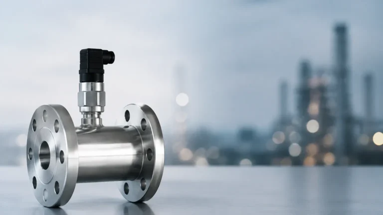
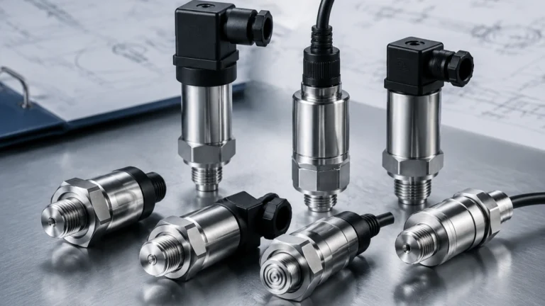
Gas Flow Meter with 4-20 Ma Output
Gas Flow Meter with 4-20 Ma Output
In industrial process automation, the accurate measurement of gas flow is critical for safety, efficiency, and billing. A gas flow meter with 4-20 ma output serves as the primary interface between the physical process and the control system. This standardized analog signal allows for seamless integration into Programmable Logic Controllers (PLCs), Distributed Control Systems (DCS), and data loggers, providing real-time monitoring of gas consumption, leakage, or process feed rates.
Understanding the underlying measurement principles and the technical nuances of the 4-20 mA signal is essential for engineers and plant managers when selecting the right instrumentation for their facility. This guide explores the different technologies available, their selection criteria, and the practical considerations for installation and maintenance.
Measurement Principles for Gas Flow
Before selecting a gas flow meter with 4-20 ma output, it is necessary to understand how different sensors translate gas movement into an electrical signal. Unlike liquids, gases are compressible, meaning their volume changes significantly with pressure and temperature. Therefore, many flow meters are designed to measure either "actual" flow or "mass" flow.
Thermal Mass Flow Measurement
Thermal mass flow meters operate on the principle of thermal dispersion. The sensor typically consists of two Resistance Temperature Detectors (RTDs). One is a reference sensor that measures the gas temperature, while the other is a heated sensor. As gas flows past the heated sensor, it carries away heat. The instrument measures the amount of power required to maintain a constant temperature differential between the two sensors.
Because heat dissipation is directly related to the number of gas molecules passing by, this technology provides a direct mass flow measurement without the need for additional pressure or temperature compensation. This makes it highly effective for applications like nitrogen blanketing or compressed air monitoring.
Vortex Shedding
Vortex flow meters utilize the Kármán vortex street principle. When a gas flows past a non-streamlined "bluff body" placed in the pipe, vortices are shed alternately on each side. The frequency of these vortices is directly proportional to the velocity of the gas. A piezoelectric crystal or similar sensor detects these pressure pulses and converts them into a flow rate. Vortex meters are robust and have no moving parts, making them suitable for high-temperature and high-velocity steam or gas applications.
Differential Pressure (DP) Flow
Differential pressure measurement is one of the most established methods. By placing a restriction in the pipe—such as an orifice plate, Venturi tube, or Pitot tube—a pressure drop is created. According to Bernoulli’s equation, the square root of this pressure drop is proportional to the flow rate. While reliable, DP meters often require external pressure and temperature sensors to calculate the compensated mass flow, and the 4-20 mA output is typically generated by a multivariable transmitter.
Ultrasonic (Transit-Time)
Ultrasonic gas flow meters use transducers to send sound pulses across the pipe. The pulse traveling with the flow moves faster than the pulse traveling against it. The difference in transit time is used to calculate the gas velocity. These meters are non-intrusive and offer a wide turn-down ratio, though they can be more sensitive to gas composition changes compared to thermal or vortex types.
Technical Advantages of the 4-20 mA Signal
The 4-20 mA current loop remains the industry standard for gas flow meter output for several technical reasons. Unlike voltage-based signals (e.g., 0-10V), current loops are highly resistant to electromagnetic interference (EMI) and signal degradation over long distances.
1. Noise Immunity: In industrial environments filled with motors and high-voltage equipment, electrical noise is prevalent. A current signal is not affected by the resistance of the wire or induced voltage spikes, ensuring the integrity of the flow data.
2. Live Zero (4mA): The use of 4mA to represent zero flow allows the system to distinguish between a "zero flow" condition and a "broken wire" condition. If the signal drops to 0mA, the control system immediately recognizes a fault.
3. Loop Powering: Many gas flow meters are "two-wire" devices, meaning they draw their operating power directly from the 4-20 mA loop, simplifying wiring and reducing installation costs.
4. Scaling: The signal is linear. For a meter calibrated from 0 to 1000 Nm³/h (Normal cubic meters per hour), 4mA represents 0 Nm³/h, 12mA represents 500 Nm³/h, and 20mA represents 1000 Nm³/h.
Selection Criteria for Industrial Applications
Choosing a gas flow meter with 4-20 ma output requires a detailed evaluation of the process conditions. Using the wrong technology can lead to inaccuracies or premature sensor failure.
Selection Comparison Table
| Technology | Typical Accuracy | Turn-down Ratio | Best For | Limitations |
| :— | :— | :— | :— | :— |
| Thermal Mass | ±1% of Reading | 100:1 | Low flow, Nitrogen, CO2 | Requires clean, dry gas |
| Vortex | ±1% to 1.5% | 20:1 | High temp, Steam, Air | High pressure drop at high flow |
| DP (Orifice) | ±2% to 3% | 4:1 | General purpose, large pipes | Limited rangeability |
| Ultrasonic | ±0.5% to 1% | 50:1 | Custody transfer, Natural gas | High initial cost |
Key Evaluation Factors
* Gas Composition: Is the gas a single component (e.g., Oxygen) or a mixture (e.g., Biogas)? Thermal meters must be calibrated for the specific gas mix, whereas vortex meters are less sensitive to composition changes.
* Flow Range: The "turn-down ratio" defines the range between the maximum and minimum measurable flow. If your process has high variability, a thermal or ultrasonic meter is preferable.
* Process Temperature and Pressure: Ensure the meter body and sensors are rated for the maximum expected pressure (in bar or PSI) and temperature (Celsius or Fahrenheit).
* Output Requirements: While 4-20 mA is standard, consider if you also need HART protocol, Modbus, or pulse outputs for totalization.
Installation Best Practices and Configuration
To ensure the gas flow meter with 4-20 ma output provides accurate data, strict adherence to installation guidelines is required. Most measurement errors are caused by improper placement rather than sensor failure.
Straight Pipe Requirements
Flow meters require a "developed flow profile" to measure accurately. Turbulence caused by elbows, valves, or reducers can distort the reading. A general rule of thumb is to have at least 10 diameters (10D) of straight pipe upstream and 5 diameters (5D) downstream of the meter. If these distances cannot be met, flow conditioners or honeycombs may be necessary.
Orientation and Mounting
For gas applications, the meter should ideally be installed in a horizontal pipe. If moisture or condensate is present in the gas line, the sensor should be mounted on the top or side of the pipe to prevent liquid from pooling on the sensor head. In vertical pipes, the flow should generally be upward to ensure a consistent profile.
Wiring and Grounding
Use shielded twisted-pair cables for the 4-20 mA loop to further minimize noise. The shield should be grounded at only one end (usually the control room side) to prevent ground loops. Ensure the power supply provides sufficient voltage to overcome the total loop resistance, which includes the meter, the wires, and the input impedance of the PLC.
Limitations and Potential Risks
While highly versatile, a gas flow meter with 4-20 ma output is not without its challenges. Users should be aware of the following risks:
* Condensation: In many gas systems, such as biogas or compressed air, moisture can condense into droplets. For thermal mass meters, these droplets can cause significant measurement spikes as the water absorbs more heat than the gas. Coalescing filters are often required.
* Calibration Drift: Over time, sensors may become coated with process contaminants or experience electronic drift. Regular verification or recalibration is necessary to maintain accuracy.
* Pressure Drop: Some meters, like orifice plates or vortex meters with reducers, introduce a permanent pressure loss in the system. This can increase energy costs for compressors or blowers.
* Gas Velocity Limits: Vortex meters require a minimum velocity to begin shedding vortices. If the flow is too low, the meter will output 4mA (zero) even if gas is moving.
Frequently Asked Questions (FAQs)
Q: Can I use a gas flow meter with 4-20 ma output for hazardous areas?
A: Yes, but you must select a meter with the appropriate explosion-proof or intrinsically safe certifications (e.g., ATEX, IECEx). These often require the use of a safety barrier in the 4-20 mA loop.
Q: How do I convert the 4-20 mA signal back to a flow rate in my PLC?
A: You use a scaling function. For example, if the meter range is 0-500 m³/h, the formula is: `Flow = (Current – 4) / 16 * 500`. Most modern PLCs have built-in blocks for this calculation.
Q: What happens if the gas composition changes?
A: For thermal mass meters, a change in gas composition (e.g., a change in the methane-to-CO2 ratio in biogas) will lead to direct errors because the thermal properties change. Vortex and DP meters are less affected by composition but may require density compensation.
Q: Is 4-20 mA better than Modbus for gas flow?
A: 4-20 mA is simpler and more robust for basic control. Modbus or other digital protocols provide more data, such as temperature, pressure, and diagnostic codes, but require more complex configuration.
Conclusion and Next Steps
Selecting the appropriate gas flow meter with 4-20 ma output is a balance between technical requirements and budget constraints. By understanding the measurement principles—whether thermal, vortex, or differential pressure—and ensuring proper installation, operators can achieve reliable data for their process control needs.
In many industrial setups, flow measurement is closely integrated with level measurement, particularly in tank farm management and chemical processing. For more detailed technical specifications and to explore our full range of industrial instrumentation, including radar and ultrasonic solutions, you can visit our Main Page. Confirming your gas type, pipe size, and expected flow ranges with a technical expert is the recommended next step before finalizing any equipment purchase.