Headbox
Headbox
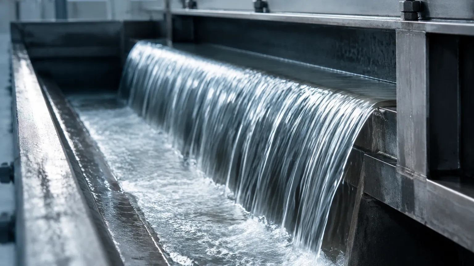
In the pulp and paper industry, the headbox serves as the critical interface between the stock preparation system and the paper machine wire. Its primary function is to transform the incoming pulp slurry—a mixture of fibers and water—into a uniform, high-velocity jet that is distributed across the full width of the forming fabric. Achieving a consistent paper weight (basis weight) and moisture profile depends heavily on the precise control of the level and pressure within this component.
For process engineers and instrumentation specialists, selecting the correct level measurement technology for a headbox is a fundamental requirement for operational stability. This article examines the measurement principles, selection criteria, and installation best practices for level sensors in headbox applications.
Measurement Principles for Headbox Level
Level measurement in a headbox is complicated by the presence of pressurized air pads, high-consistency pulp, and the need for extreme hygiene and smoothness to prevent fiber buildup. There are three primary physical principles used to monitor these levels: hydrostatic pressure, microwave reflection (radar), and ultrasonic wave propagation.
1. Hydrostatic Pressure (Differential Pressure)
Hydrostatic level measurement relies on the principle that the pressure at a specific point in a liquid is proportional to the height of the liquid column above it. The formula used is $P = \rho \cdot g \cdot h$, where $P$ is pressure, $\rho$ is the density of the fluid, $g$ is gravity, and $h$ is the height of the liquid.
In a pressurized headbox, a single pressure sensor is insufficient because the air pad above the slurry also exerts pressure. Therefore, a Differential Pressure (DP) transmitter is employed. One side of the transmitter (the high-pressure side) is connected to the bottom of the headbox to measure the combined pressure of the liquid and the air pad. The other side (the low-pressure side) is connected to the top of the headbox to measure only the air pad pressure. The transmitter subtracts the air pressure from the total pressure, leaving the hydrostatic pressure of the pulp slurry, which is then converted into a level reading.
2. Non-Contacting Radar (FMCW)
Radar level meters use Frequency Modulated Continuous Wave (FMCW) technology. The sensor emits a continuous microwave signal that changes in frequency over time. The signal reflects off the surface of the pulp slurry and returns to the sensor. By measuring the frequency difference between the emitted and received signals, the device calculates the distance to the surface with high precision.
Radar is increasingly preferred for headbox applications because it is non-contact. This means the sensor is not subject to the corrosive or abrasive nature of the pulp, and there are no mechanical parts that can cause "stringing" or fiber hang-ups.
3. Ultrasonic Level Sensing
Ultrasonic sensors function similarly to radar but use sound waves instead of electromagnetic waves. A transducer emits a sound pulse that reflects off the liquid surface. The time-of-flight (ToF) is used to determine the distance. While cost-effective, ultrasonic sensors in a headbox environment can be affected by changes in air temperature, pressure, and the presence of heavy foam, which can absorb the sound energy.
Technology Selection for Different Headbox Types
Headboxes are generally categorized into open (atmospheric) and closed (pressurized) systems. The choice of instrumentation depends largely on these mechanical configurations.
Selection Table: Level Measurement Technologies
| Feature | Hydrostatic (DP) | Non-Contact Radar | Ultrasonic |
| :— | :— | :— | :— |
| Measurement Range | Up to 10m (32.8 ft) | Up to 30m+ (98 ft+) | Up to 15m (49 ft) |
| Accuracy | ±0.075% to ±0.1% | ±1 mm to ±2 mm | ±0.25% of range |
| Pressure Limit | High (Up to 400 bar) | Moderate (Up to 40 bar) | Atmospheric |
| Foam Resistance | Excellent | Good (with 80GHz) | Poor |
| Maintenance | Requires cleaning | Very Low | Low |
| Typical Application | Pressurized Headbox | Modern High-Speed Lines | Open Headboxes |
Key Evaluation Criteria
When evaluating level instrumentation for a headbox project, engineers must prioritize the following factors:
1. Chemical Compatibility: The pulp slurry often contains bleaching agents, fillers, and additives. Wetted parts, such as the diaphragms of DP transmitters, should be made of 316L stainless steel, Hastelloy, or Tantalum to prevent corrosion.
2. Surface Turbulence: High-speed paper machines involve significant turbulence within the headbox. Radar sensors with advanced signal processing algorithms are required to filter out surface agitation and provide a stable average level.
3. Foam Layers: Many papermaking processes generate foam. Hydrostatic sensors are unaffected by foam as they measure mass/pressure. However, for radar, a high-frequency (80 GHz) signal is often necessary to penetrate the foam or distinguish the true liquid level from the foam surface.
4. Response Time: Headbox level control is a fast-loop process. The sensor must have a fast refresh rate (typically <100ms) to allow the control system to adjust the pump speed or air pad pressure in real-time.
Engineering Installation Considerations
Proper installation is as critical as the choice of technology. Incorrect mounting can lead to signal interference or mechanical failure.
Mounting for DP Transmitters
For hydrostatic measurement, a flush-mount diaphragm is essential. Traditional impulse lines (small diameter tubes) should be avoided because the wood fibers will quickly plug the lines, leading to measurement drift and failure. The transmitter should be mounted at the lowest possible point of the measurement range. If the headbox is pressurized, the compensation line (the "dry leg" or "wet leg") must be properly configured to account for the air pad pressure without allowing condensation to build up in the piping.
Mounting for Radar Sensors
Radar sensors should be installed with a clear "view" of the liquid surface. They must be positioned away from the headbox walls to avoid false reflections (echoes) from the internal structure. If the headbox has internal baffles or agitators, the sensor should be mounted in a position where the beam angle does not intersect these components. For pressurized headboxes, radar sensors are often mounted behind a PTFE or ceramic window that acts as a pressure barrier while allowing the microwave signal to pass through.
Calibration and Zero-Point Adjustment
Before startup, sensors must be calibrated to the specific geometry of the headbox. For DP transmitters, this involves setting the 4mA point at the bottom of the desired range and the 20mA point at the top. It is vital to perform a "zero trim" once the headbox is installed but empty to account for the mounting position and any static pressure effects.
Common Risks and Limitations
* Consistency Variations: Hydrostatic sensors measure the weight of the fluid. If the pulp consistency (density) changes significantly without being compensated for in the control logic, the level reading will be inaccurate.
* Vibration: Paper machines generate significant mechanical vibration. Instrumentation must be rated for high-vibration environments, or remote-mounted electronics should be used to protect the sensitive circuit boards.
* Condensation: In the humid environment of a paper mill, condensation can form on the lens of a radar or ultrasonic sensor. Selecting a sensor with a drip-off lens design or a purging connection (using dry air) can mitigate this risk.
Frequently Asked Questions (FAQ)
Q: How often should headbox level sensors be calibrated?
A: In most stable operations, an annual calibration check is sufficient. However, if there are significant changes in the grade of paper being produced (which affects slurry density), the hydrostatic sensors may require more frequent checks.
Q: Can I use a radar sensor in a headbox with a heavy steam blanket?
A: Yes, radar is largely unaffected by steam because microwaves do not rely on the air medium for travel. However, ensure the sensor is rated for the high temperatures associated with the steam.
Q: Why is 80 GHz radar better than 26 GHz for a headbox?
A: 80 GHz radar has a much narrower beam angle (typically around 3 to 4 degrees). This allows the sensor to be installed in smaller nozzles and avoids interference from internal headbox structures like distributors or walls.
Conclusion and Next Steps
The headbox is a high-precision component where even minor level fluctuations can result in paper defects or machine downtime. For modern, high-speed paper production, non-contact radar offers the lowest maintenance and highest reliability, while hydrostatic DP transmitters remain the standard for many pressurized applications due to their robustness and ability to ignore foam.
When planning an upgrade or a new installation, it is essential to verify the chemical properties of the stock, the internal geometry of the headbox, and the specific pressure requirements of the air pad system. For comprehensive technical specifications and to explore the full range of instrumentation, engineers can visit the Main Page to review product options and application support. Ensuring that the chosen sensor aligns with the specific dynamics of the pulp and paper process is the most effective way to guarantee long-term accuracy and production efficiency.