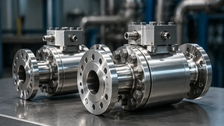
High Frequency Pressure Transducer
High Frequency Pressure Transducer
In the field of industrial automation and process control, the ability to monitor rapid changes in pressure is critical for maintaining system integrity and optimizing performance. While standard pressure sensors are sufficient for steady-state measurements, applications involving explosions, combustion, high-speed hydraulics, or rapid fluid transients require a specialized instrument: the high frequency pressure transducer. These devices are engineered to capture pressure fluctuations that occur within microseconds, providing the data necessary to analyze dynamic phenomena that slower sensors would simply filter out.
For engineers and system integrators, selecting a high frequency pressure transducer involves understanding the delicate balance between sensitivity, natural frequency, and environmental resilience. This guide explores the fundamental principles, selection criteria, and practical application of these high-speed instruments within the broader context of industrial measurement and level control systems.
Measurement Principles of High Frequency Transducers
To understand how a high frequency pressure transducer operates, one must first distinguish between static and dynamic pressure measurement. Static pressure changes slowly over time, whereas dynamic pressure involves rapid oscillations or shock waves. The frequency response of a transducer determines its ability to track these changes accurately.
Piezoelectric Sensing
Piezoelectric transducers are the industry standard for high-frequency applications. They utilize crystals (such as quartz) or ceramic materials that generate an electrical charge when subjected to mechanical stress. Because these materials are extremely stiff, they possess a very high natural frequency—often exceeding 100 kHz or even 500 kHz. This stiffness allows the sensor to respond almost instantaneously to pressure waves. However, piezoelectric sensors are inherently AC-coupled, meaning they are excellent for measuring pressure changes but cannot measure static pressure over long periods due to charge leakage.
Piezoresistive Sensing (Silicon-on-Insulator)
For applications requiring the measurement of both static and high-speed dynamic pressure, piezoresistive transducers are used. These sensors employ a micro-machined silicon diaphragm with integrated resistors. When pressure deforms the diaphragm, the resistance changes (the piezoresistive effect). Modern high-frequency piezoresistive sensors use "thin-film" or "Silicon-on-Insulator" (SOI) technology to minimize the mass of the sensing element, allowing for frequency responses in the range of 10 kHz to 100 kHz. Unlike piezoelectric sensors, these can provide a constant output for a steady pressure level.
The Importance of Natural Frequency
A transducer's natural frequency is the rate at which its internal components vibrate when disturbed. To ensure measurement accuracy, the frequency of the pressure event being measured should typically not exceed 20% of the transducer's natural frequency. If the input frequency approaches the natural frequency, the sensor may oscillate (ring), leading to significant measurement errors and potential mechanical failure.
Technical Selection Criteria
Choosing the correct high frequency pressure transducer requires a detailed analysis of the process environment and the expected signal characteristics. The following table provides a comparison of common sensing technologies used in high-speed applications:
| Feature | Piezoelectric (PE) | Piezoresistive (PR) | Strain Gauge (Thin Film) |
| :— | :— | :— | :— |
| Measurement Type | Dynamic Only | Static & Dynamic | Static & Low-Dynamic |
| Frequency Range | 1 Hz to >500 kHz | 0 Hz to 100 kHz | 0 Hz to 5 kHz |
| Temperature Range | Up to 350°C (Specialized) | Up to 150°C | Up to 200°C |
| Signal Output | Charge or Voltage (IEPE) | mV/V, 4-20mA, 0-10V | 4-20mA, 0-5V |
| Durability | Very High | Moderate | High |
| Common Use Case | Blast testing, Turbines | Hydraulics, Engine Testing | Process Level, Pipelines |
Sampling Rate and Data Acquisition
A high frequency pressure transducer is only as effective as the data acquisition (DAQ) system it is connected to. According to the Nyquist-Shannon sampling theorem, the DAQ must sample at a rate at least twice the highest frequency of interest. In practice, for industrial troubleshooting, engineers often sample at 5 to 10 times the highest frequency to accurately reconstruct the pressure waveform.
Integration with Level Measurement Systems
While high-frequency transducers are often associated with aerospace or ballistics, they play a vital role in industrial level measurement and fluid management. In large-scale tank farms or complex piping networks, rapid valve closures can cause "water hammer"—a high-pressure surge that can rupture pipes or damage sensitive level sensors.
By installing a high frequency pressure transducer alongside standard hydrostatic level transmitters, operators can detect these transients in real-time. This allows for the implementation of surge tanks or slow-closing valves to protect the system. For a comprehensive look at how these technologies integrate into broader industrial monitoring, you can Review product options and application support on our Main Page.
Installation Considerations
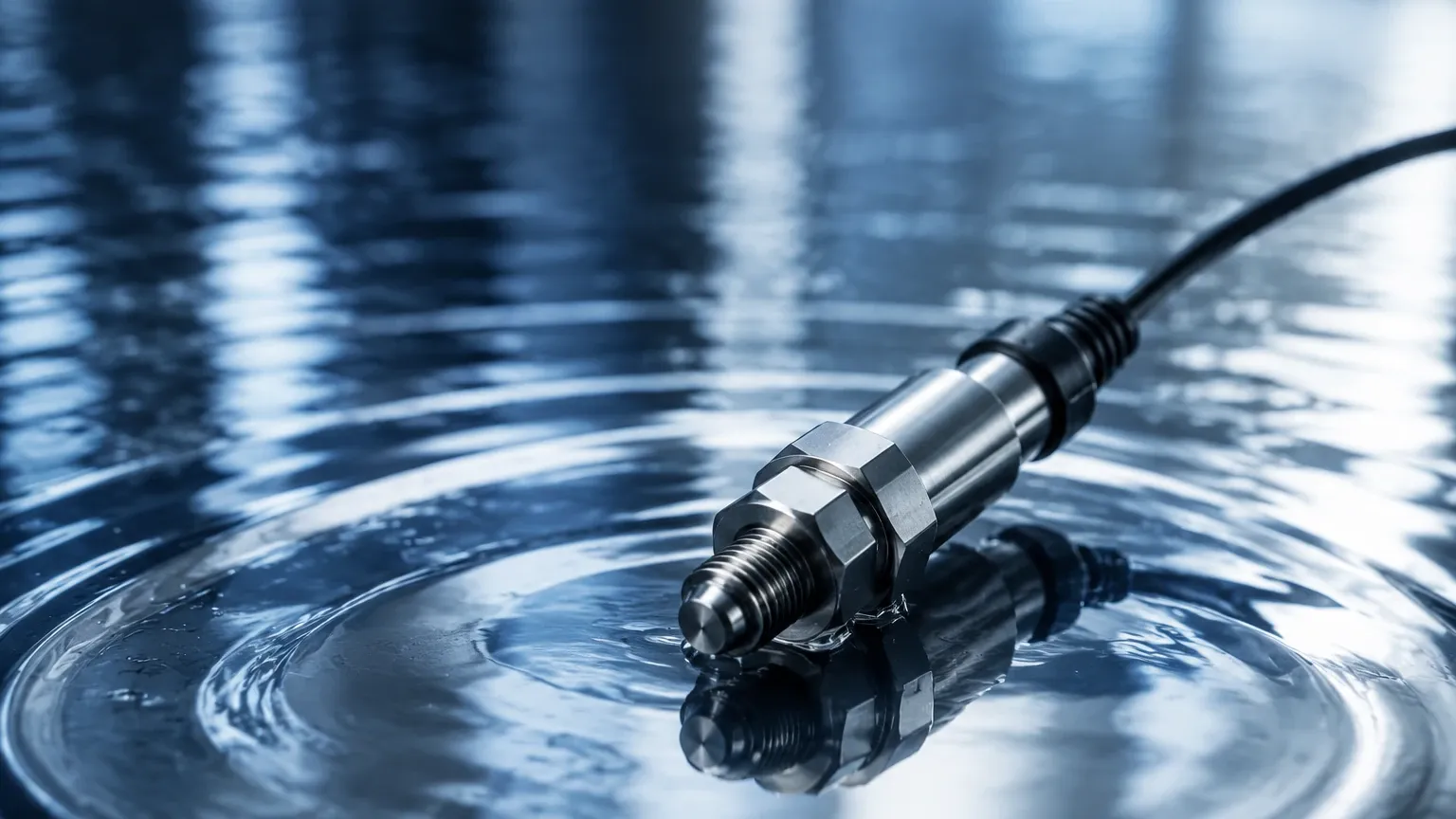
The physical installation of a high frequency pressure transducer is more critical than that of a standard sensor. Improper mounting can introduce mechanical noise or create "dead volume" that dampens the high-frequency signal.
1. Flush Mounting: To capture the fastest transients, the sensor diaphragm should be mounted flush with the inner wall of the pipe or vessel. Any recessed cavity (a "stagnant pocket") acts as a Helmholtz resonator, which can attenuate high-frequency signals and introduce false resonance peaks.
2. Cabling and Noise: High-frequency signals are susceptible to electromagnetic interference (EMI). Use shielded twisted-pair cabling and ensure proper grounding. For piezoelectric sensors, low-noise coaxial cables are required to prevent "triboelectric noise" caused by cable movement.
3. Thermal Protection: Rapid pressure changes are often accompanied by rapid temperature changes (adiabatic heating). If the sensor is exposed to thermal flashes, it may produce a "thermal transient" error. In such cases, a thin coating of silicone grease or an ablative material on the diaphragm can provide momentary thermal insulation without significantly affecting the frequency response.
4. Torque Sensitivity: Many high-frequency sensors are sensitive to mounting torque. Over-tightening can stress the sensor housing and shift the zero-point calibration. Always use a calibrated torque wrench and follow the manufacturer’s specifications in Newton-meters (Nm).
Limitations and Common Risks
Despite their capabilities, high frequency pressure transducers have specific limitations that must be managed:
* Fragility of Thin Diaphragms: To achieve high frequency, diaphragms must be thin and light. This makes them more susceptible to damage from particulates in the fluid or over-pressure events.
* Signal Conditioning Complexity: Piezoelectric sensors require charge amplifiers or IEPE (Integrated Electronics Piezo-Electric) power supplies. This adds complexity and cost to the instrumentation chain compared to a simple 4-20mA loop.
* Data Overload: High-speed sampling generates vast amounts of data. Systems must be designed to handle the storage and processing requirements, often utilizing "trigger-based" recording where the system only saves data when a certain pressure threshold is exceeded.
Frequently Asked Questions (FAQ)
Q: Can I use a high frequency pressure transducer for standard tank level monitoring?
A: While possible, it is generally not cost-effective. High-frequency sensors are designed for transients. For steady-state level monitoring, a standard hydrostatic level transmitter or ultrasonic sensor is more appropriate. However, they are excellent for monitoring the *dynamics* of a filling process to prevent overfill surges.
Q: What is IEPE?
A: IEPE stands for Integrated Electronics Piezo-Electric. It is a standard for piezoelectric sensors that includes an internal amplifier, allowing the sensor to output a low-impedance voltage signal that can be transmitted over long cables without special low-noise wiring.
Q: How often should these sensors be calibrated?
A: Because high-frequency sensors often operate in harsh, high-impulse environments, annual calibration is recommended. For critical safety applications, such as blast monitoring, pre- and post-test calibrations are common.
Q: Does the media (liquid vs. gas) affect the frequency response?
A: Yes. The speed of sound in the media and the density of the fluid affect how pressure waves reach the sensor. Liquids, being less compressible, transmit shock waves more efficiently than gases, which can place higher mechanical stress on the transducer diaphragm.
Conclusion
The high frequency pressure transducer is an indispensable tool for diagnosing and monitoring dynamic industrial processes. Whether it is used to protect infrastructure from water hammer or to analyze the performance of high-speed hydraulic actuators, understanding the underlying physics of the sensor is key to successful implementation. By carefully considering the natural frequency, mounting geometry, and data acquisition requirements, engineers can gain deep insights into the transient behaviors of their systems, ensuring both safety and efficiency.