Hydrostatic Level Transducer
Hydrostatic Level Transducer
In the landscape of industrial process control, the hydrostatic level transducer remains one of the most reliable and widely adopted technologies for liquid level measurement. From municipal water treatment to complex chemical processing, these instruments provide a robust method for determining the height of a liquid based on the physical relationship between pressure and depth. This guide explores the engineering principles, selection criteria, and practical installation requirements for hydrostatic level transducers in modern industrial applications.
The Fundamental Principle of Hydrostatic Measurement
Hydrostatic level measurement is based on the principle that the pressure at a specific point within a static liquid is proportional to the height of the liquid column above that point. This relationship is governed by the hydrostatic pressure formula:
P = ρ × g × h
Where:
* P is the hydrostatic pressure (typically measured in bar or pascals).
* ρ (rho) is the density of the liquid (kg/m³).
* g is the acceleration due to gravity (approximately 9.81 m/s²).
* h is the height of the liquid column (meters).
In a practical industrial setting, the hydrostatic level transducer measures the pressure exerted by the liquid. Since gravity is constant and the density of the liquid is usually known, the sensor's electronics can calculate the height (h) with high precision. For example, in a water tank with a density of 1000 kg/m³, every 1 meter (3.28 ft) of depth generates approximately 0.098 bar (1.42 psi) of pressure.
Atmospheric Pressure Compensation
One critical aspect of hydrostatic measurement is the influence of atmospheric pressure. In an open tank or reservoir, the total pressure acting on the sensor is the sum of the liquid's hydrostatic pressure plus the ambient atmospheric pressure. To ensure accuracy, the transducer must subtract the atmospheric pressure to provide a "gauge pressure" reading that reflects only the liquid level.
Most submersible transducers achieve this through a vented cable. This cable contains a small capillary tube that allows the internal side of the sensor diaphragm to be exposed to the current atmospheric pressure, effectively canceling out its influence on the measurement. In closed-tank applications, differential pressure (DP) transmitters are often used instead, measuring the difference between the bottom liquid pressure and the top gas-space pressure.
Types of Hydrostatic Level Transducers
Depending on the installation environment and the nature of the liquid, engineers typically choose between two primary configurations: submersible and externally mounted sensors.
1. Submersible Transducers
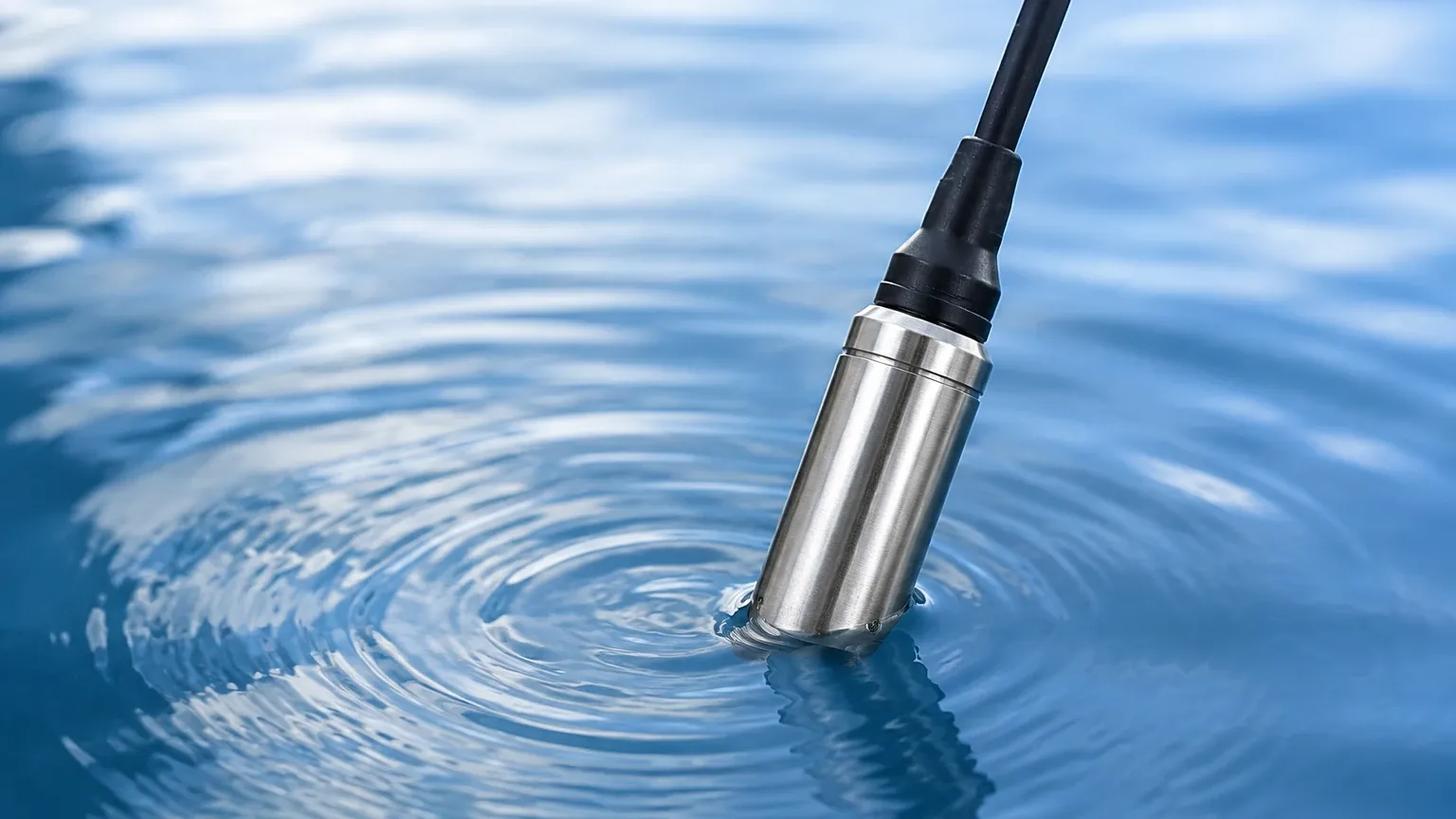
These units are designed to be lowered directly into the liquid. They feature a high IP rating (usually IP68) and a hermetically sealed housing. The sensor is suspended by its own reinforced cable, which also carries the signal and the atmospheric vent tube. These are ideal for deep wells, boreholes, reservoirs, and wastewater lift stations where side-wall access is impossible.
2. Externally Mounted (Tank) Transducers
These sensors are mounted to the outside of a tank via a threaded connection or a flange. They are commonly used in process tanks where the sensor can be isolated by a valve for maintenance without draining the vessel. These are often referred to as pressure transmitters and are preferred in chemical applications where the sensor body needs to be kept away from the bulk of the fluid.
Practical Selection Table for Industrial Applications
Choosing the right hydrostatic level transducer requires balancing technical requirements with budget constraints. The following table provides a comparison based on common industrial scenarios.
| Application | Recommended Sensor Type | Diaphragm Material | Considerations |
| :— | :— | :— | :— |
| Clean Water Reservoir | Submersible | 316L Stainless Steel | Cost-effective, easy installation. |
| Wastewater / Sludge | Submersible (Large Diaphragm) | 316L or Ceramic | Requires non-clogging design; high durability. |
| Corrosive Chemicals | Flanged / External | Tantalum or PTFE coated | Material compatibility is the priority. |
| Deep Boreholes | Slim Submersible | Stainless Steel | High pressure range; reinforced cable strength. |
| Food & Beverage | Hygienic Flanged | 316L (Electropolished) | Must meet CIP/SIP cleaning requirements. |
| Fuel Storage | Submersible (Ex-rated) | 316L Stainless Steel | Requires Intrinsically Safe (IS) certification. |
Key Evaluation Criteria for Engineering Projects
When specifying a hydrostatic level transducer, engineers must look beyond the basic pressure range. Several factors influence the long-term reliability and accuracy of the device.
Material Compatibility
The wetted parts—including the sensor diaphragm, the housing, and the cable jacket (for submersible types)—must be chemically compatible with the process fluid. While 316L stainless steel is the standard, aggressive media like hydrochloric acid or seawater may require Hastelloy, Tantalum, or Ceramic sensors. Cable jackets are typically available in PVC, PUR (Polyurethane), or FEP (Fluorinated Ethylene Propylene), with FEP offering the highest chemical resistance.
Accuracy and Stability
Industrial transducers usually offer accuracy classes ranging from 0.5% to 0.1% of the full scale. It is important to consider "long-term stability," which indicates how much the sensor's calibration might drift over a year. High-quality sensors from reputable manufacturers like Welk ensure minimal drift, reducing the frequency of re-calibration.
Signal Output and Integration
Modern systems typically require a 4-20mA analog signal, often with HART protocol for remote configuration and diagnostics. In smart factories and remote monitoring sites, RS485 Modbus RTU is becoming increasingly popular due to its ability to daisy-chain multiple sensors over long distances with minimal wiring.
For those evaluating different technologies for a specific project, it is helpful to Review product options and application support to ensure the selected instrument meets all local regulatory and technical standards.
Installation Considerations and Best Practices
Proper installation is as important as the sensor selection itself. Even the most accurate hydrostatic level transducer will provide poor data if installed incorrectly.
1. Avoid Turbulence: In tanks with agitators or high-velocity inflows, the sensor should be mounted inside a "stilling well" (a perforated pipe). This protects the diaphragm from physical buffeting and ensures a stable pressure reading.
2. Cable Management: For submersible sensors, the cable should be secured with a proper cable clamp to prevent stretching or damage to the internal vent tube. The vent tube itself must terminate in a dry environment, usually inside a junction box with a desiccant filter to prevent moisture from entering and causing internal corrosion.
3. Positioning: The sensor should not sit directly on the bottom of a tank or well where silt and sediment can accumulate. It should be suspended at least 100mm to 300mm (4 to 12 inches) above the bottom to prevent the diaphragm from being buried.
4. Zeroing the Sensor: After installation, the sensor should be zeroed to account for its specific vertical position and the weight of the cable. Most digital transducers allow for an easy offset adjustment via software or a local display.
Limitations and Risks
While highly versatile, the hydrostatic level transducer is not a universal solution. Engineers must be aware of its inherent limitations:
* Density Sensitivity: Because the measurement relies on the formula P = ρgh, any change in liquid density (ρ) will result in a measurement error. If a tank's temperature fluctuates significantly, the density changes, and the level reading will drift even if the actual volume remains constant.
* Pressurized Vessels: In closed tanks where the head-space is pressurized (e.g., a boiler or a pressurized fuel tank), a standard hydrostatic transducer cannot be used alone. A differential pressure system is required to subtract the top pressure from the bottom pressure.
* Build-up and Clogging: In liquids with high solids content or those that tend to crystallize, the sensor diaphragm can become coated. This "build-up" adds mechanical stress to the diaphragm, leading to false high readings or complete sensor failure.
Frequently Asked Questions (FAQ)
Q: How often should a hydrostatic level transducer be calibrated?
A: For most industrial applications, an annual calibration check is sufficient. However, in critical safety applications or highly corrosive environments, semi-annual checks are recommended to ensure the diaphragm has not suffered from mechanical fatigue or chemical degradation.
Q: Can I use a hydrostatic sensor for boiling liquids?
A: It is generally not recommended. Boiling liquids have highly unstable densities and significant vapor pressure. Furthermore, the high temperature may exceed the operating limits of the sensor's internal electronics. Radar or high-temperature capacitive sensors are usually better suited for such environments.
Q: What happens if the vent tube in the cable gets blocked?
A: If the vent tube is blocked or kinked, the sensor can no longer compensate for changes in atmospheric pressure. This can lead to errors of several centimeters (or inches) in the level reading as the local weather changes (high-pressure vs. low-pressure systems).
Q: Is it possible to shorten the cable of a submersible transducer?
A: Yes, but it must be done carefully. The vent tube must remain open and protected. It is usually better to coil the excess cable at the top of the installation rather than cutting it, as the factory seal and calibration are often optimized for the original cable length.
Conclusion
The hydrostatic level transducer remains a cornerstone of liquid level monitoring due to its simplicity and reliability. By understanding the relationship between pressure and depth, and by carefully selecting materials and installation methods, process engineers can achieve high-precision measurements in a wide variety of industrial settings. When accuracy and durability are paramount, consulting with a specialized manufacturer like Welk ensures that the chosen solution is tailored to the specific demands of the application.