Inline Cip Sensors
Inline Cip Sensors
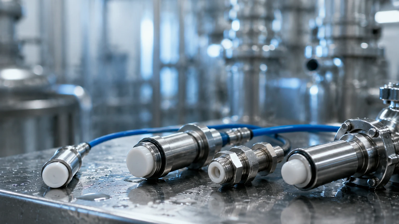
In modern industrial processing, Clean-In-Place (CIP) systems are essential for maintaining hygiene and operational efficiency without the need to disassemble complex piping or vessel networks. At the heart of these automated cleaning cycles are inline CIP sensors. These instruments provide real-time data on the state of the cleaning process, ensuring that every cycle meets stringent safety standards while minimizing the waste of water, energy, and chemical detergents. For engineers and plant managers, selecting the right inline CIP sensors is a critical step in optimizing process automation and protecting product integrity.
The Role of Inline Monitoring in CIP Cycles
CIP systems typically follow a multi-stage sequence: a pre-rinse to remove bulk soil, a caustic wash to dissolve organic fats and proteins, an intermediate rinse, an acid wash to remove mineral scale, and a final rinse with high-purity water. Inline CIP sensors are integrated directly into the process piping to monitor the transition between these phases.
By measuring parameters such as conductivity, turbidity, and temperature in real-time, these sensors allow the control system to determine exactly when a phase is complete. This prevents the "over-cleaning" that leads to excessive chemical consumption and the "under-cleaning" that risks batch contamination. For comprehensive industrial level measurement and automation support, engineers often consult the Main Page of specialized manufacturers to integrate these sensors into broader vessel management systems.
Core Measurement Principles for Inline CIP Sensors
Understanding the physical principles behind these sensors is vital for proper selection and application.
1. Inductive Conductivity Measurement
Conductivity is the primary method for identifying cleaning agents. Caustic (NaOH) and acid (HNO3) solutions have high ionic concentrations, making them highly conductive.
* Principle: Most inline CIP sensors use inductive (toroidal) technology. An internal coil generates an alternating magnetic field, inducing a voltage in the surrounding liquid. A second coil measures the resulting current, which is proportional to the liquid's conductivity.
* Advantage: Unlike contact-based sensors, inductive sensors have no exposed electrodes, making them resistant to fouling and polarization in harsh chemical environments.
2. Turbidity (Optical) Measurement
Turbidity sensors measure the clarity of the fluid, which is essential during the pre-rinse and final rinse stages.
* Principle: These sensors emit light (usually infrared) into the medium. If particles or soil are present, the light scatters. Detectors measure the light at specific angles (e.g., 90° or 180°).
* Application: In CIP, turbidity sensors detect the transition from product to water, allowing for precise "product recovery" and ensuring the final rinse water is free of residual soil.
3. Temperature and Flow Sensing
Cleaning chemistry is highly dependent on temperature. Most inline CIP sensors include integrated Pt100 or Pt1000 RTDs to ensure the caustic wash reaches the required 70°C to 85°C (158°F to 185°F). Flow sensors ensure that the cleaning fluid reaches the necessary turbulent velocity—typically 1.5 to 2.1 m/s (5 to 7 ft/s)—to provide the mechanical scrubbing action required for pipe walls.
Technical Selection and Comparison
When evaluating inline CIP sensors, engineers must balance sensitivity with durability. The following table provides a comparison of common sensor types used in CIP loops:
| Sensor Type | Primary Parameter | Measurement Range | Typical Application |
| :— | :— | :— | :— |
| Inductive Conductivity | Concentration | 0.5 to 1000 mS/cm | Chemical dosing, phase separation |
| Optical Turbidity | Clarity / Solids | 0 to 4000 NTU | Product recovery, rinse water monitoring |
| Hygienic Pressure | Pipe Pressure | -1 to 40 bar | Pump protection, leak detection |
| Thermal Flow | Velocity | 0.1 to 3 m/s | Ensuring turbulent flow for scrubbing |
Key Evaluation Criteria for Inline CIP Sensors
Selecting a sensor for a hygienic environment requires more than just measuring accuracy. The physical design must prevent the sensor itself from becoming a source of contamination.
Hygienic Design and Materials
All wetted parts must be constructed from food-grade materials. The industry standard is 316L (1.4404) stainless steel or high-performance plastics like PEEK (Polyether ether ketone). PEEK is favored for conductivity sensor tips because it is chemically inert and can withstand the thermal shock of switching from cold water to hot caustic.
Surface Finish and Certifications
To prevent bacterial growth, the surface roughness (Ra) of the sensor must be less than 0.8 μm (32 μin). Look for sensors that carry EHEDG (European Hygienic Engineering & Design Group) or 3-A Sanitary Standards certifications. These ensure the sensor is designed for easy cleaning and has no "dead spaces" where product can stagnate.
Process Connections
Inline CIP sensors must be mounted using hygienic fittings that eliminate crevices. Common options include:
* Tri-Clamp: The most common standard in North America.
* Varivent: A versatile flange system popular in European beverage and dairy plants.
* DIN 11851: Threaded hygienic couplings.
Installation Guidelines and Best Practices
Proper installation is critical to the performance of inline CIP sensors. A poorly placed sensor will provide inaccurate readings and may fail prematurely.
1. Avoid Dead Legs: Sensors should be installed in a way that allows the cleaning fluid to flow fully across the sensing face. Avoid mounting sensors in long T-junctions where the fluid might stagnate.
2. Orientation for Drainage: Sensors should be installed in vertical pipe sections with upward flow. This ensures the pipe is always full (no air pockets) and allows for complete self-drainage when the system is emptied.
3. Expansion and Vibration: CIP lines undergo significant thermal expansion during hot wash cycles. Ensure the sensor housing is robust enough to handle thermal stress and that the wiring is secured against pump vibrations.
4. Cable Management: Use high-quality, shielded cables to prevent electromagnetic interference (EMI) from large pump motors. In CIP environments, use cables with IP69K-rated connectors to withstand high-pressure washdowns.
Common Risks and Limitations
While inline CIP sensors are robust, they are not immune to failure. Engineers should be aware of the following risks:
* Fouling/Scaling: In hard water areas or processes with high mineral content, scale can build up on the sensor face. While inductive conductivity sensors are less sensitive to this than electrode types, heavy scaling will eventually cause a drift in accuracy.
* Thermal Shock: Rapid transitions between 5°C (41°F) rinse water and 85°C (185°F) caustic can crack lower-quality plastic sensors. Always verify the thermal shock rating of the instrument.
* Chemical Compatibility: Ensure the sensor seals (O-rings) are compatible with the specific chemicals used. EPDM is standard for most CIP applications, but FKM (Viton) may be required for fatty or oily media.
Integration with Level Measurement
While inline sensors monitor the pipes, the overall CIP strategy depends heavily on the level measurement within the chemical storage and balance tanks. Accurate level transmitters, such as the radar and ultrasonic solutions found on the Main Page, ensure that the CIP skid never runs dry and that chemical concentrations remain stable. Integrating inline data with tank level data allows for a fully closed-loop automation system.
Frequently Asked Questions (FAQ)
Q: How often should inline CIP sensors be calibrated?
A: For most food and beverage applications, an annual calibration check is standard. However, in pharmaceutical processes, semi-annual or quarterly validation may be required to meet regulatory compliance.
Q: Can one sensor measure both acid and caustic?
A: Yes. Inductive conductivity sensors can measure a wide range of concentrations. The control system (PLC) uses the conductivity value to identify which chemical is currently flowing through the line.
Q: What is the difference between 4-20mA and IO-Link sensors?
A: 4-20mA is a traditional analog signal representing one variable. IO-Link is a digital protocol that allows the sensor to transmit multiple variables (e.g., conductivity + temperature) and diagnostic data (e.g., internal error codes) over a single cable.
Q: Do inline CIP sensors require manual cleaning?
A: Ideally, no. They are designed to be cleaned by the CIP process itself. If manual cleaning is frequently required, it usually indicates a flaw in the sensor's placement or a mismatch between the sensor material and the process media.
By implementing high-quality inline CIP sensors and following best practices for installation and maintenance, industrial facilities can achieve significant savings in chemical costs and water usage while ensuring the highest levels of product safety.