Inline Ph Sensors
Inline Ph Sensors
In the landscape of industrial process control, the ability to monitor chemical properties in real-time is as critical as measuring physical parameters like pressure or volume. Inline pH sensors represent the primary technology used to achieve this, providing continuous, automated feedback on the acidity or alkalinity of a process fluid. Unlike manual grab sampling, which introduces delays and potential contamination, inline measurement allows for immediate adjustments in dosing, neutralization, and safety protocols.
For engineers and plant managers utilizing advanced instrumentation, such as the radar and ultrasonic solutions found on the Welk Main Page, understanding the synergy between liquid level and liquid chemistry is essential. This guide provides a comprehensive technical overview of inline pH sensors, their operating principles, and the engineering considerations required for successful integration into industrial piping and tank systems.
Fundamental Principles of pH Measurement
pH is a measure of the hydrogen ion activity in a solution, defined mathematically as the negative logarithm of the hydrogen ion concentration. In an industrial context, inline pH sensors operate based on the potentiometric principle, which involves measuring the voltage difference between two electrochemical half-cells: a sensing electrode and a reference electrode.
The Nernst Equation
The relationship between the measured voltage (potential) and the pH value is governed by the Nernst Equation. At a standard temperature of 25°C (77°F), a change of one pH unit corresponds to a theoretical change of 59.16 millivolts (mV). The equation is expressed as:
E = E0 – (RT/nF) ln(Q)
Where:
* E is the measured potential.
* E0 is the standard electrode potential.
* R is the universal gas constant.
* T is the absolute temperature in Kelvin.
* n is the number of electrons transferred.
* F is the Faraday constant.
Because the voltage output is temperature-dependent, industrial inline pH sensors almost always include an integrated temperature element (such as a PT100 or PT1000) to provide Automatic Temperature Compensation (ATC). Without this, the accuracy of the reading would drift significantly as the process temperature fluctuates.
The Glass Membrane Interface
The heart of the inline pH sensor is the hydrogen-ion-selective glass membrane. When this membrane is immersed in a liquid, a hydrated layer forms on both the inner and outer surfaces. An ion exchange occurs where hydrogen ions from the process fluid enter the hydrated layer, creating a charge. The difference in charge between the internal buffer solution of the sensor and the external process fluid generates the millivolt signal that the transmitter converts into a pH reading.
Key Components of an Inline pH Sensor
Modern industrial sensors are often designed as "combination electrodes," housing all necessary components within a single 12mm or 25mm diameter body. The primary components include:
1. Sensing Electrode: A glass bulb specially formulated to respond to hydrogen ions.
2. Reference Electrode: Provides a stable, known potential against which the sensing electrode is measured. It typically uses a silver/silver chloride (Ag/AgCl) system.
3. Reference Junction (Diaphragm): This is a porous point of contact that allows electrical communication between the reference electrolyte and the process fluid. Common materials include ceramic, PTFE (Teflon), or open apertures for solid polymer electrolytes.
4. Electrolyte: A conductive solution (usually Potassium Chloride, KCl) that surrounds the reference electrode. In inline applications, this is often a gel or a solid polymer to prevent the electrolyte from washing away or being contaminated by process pressure.
5. Sensor Body: Usually constructed from glass or high-performance plastics like PEEK or Ryton to withstand chemical corrosion and mechanical stress.
Selection Criteria for Industrial Applications
Choosing the correct inline pH sensor requires an analysis of the process environment. A sensor designed for clean water treatment will fail rapidly in a chemical manufacturing plant or a wastewater facility with high solids content.
Selection Table: Sensor Types vs. Application Environments
| Feature | General Purpose | High Temperature / CIP | Chemical / Poison Resistant | Wastewater / Slurry |
| :— | :— | :— | :— | :— |
| Electrolyte Type | Gel-filled | High-temp stabilized gel | Pressurized liquid or solid | Solid polymer |
| Junction Material | Ceramic | PTFE or Ceramic | Double-junction ceramic | Open aperture |
| Temperature Range | 0°C to 80°C | 0°C to 135°C | -5°C to 100°C | 0°C to 110°C |
| Max Pressure | 6 bar (87 psi) | 10 bar (145 psi) | 7 bar (101 psi) | 13 bar (188 psi) |
| Typical Use | Cooling towers, pools | Food & Beverage, Biotech | Chemical processing | Mining, heavy waste |
Considerations for Chemical Compatibility
In aggressive environments, the choice of junction and electrolyte is paramount. "Poisoning" occurs when ions from the process (such as sulfides, cyanides, or heavy metals) enter the reference junction and react with the silver ions in the reference system, forming precipitates that clog the junction and cause the sensor to fail. In such cases, a double-junction sensor or a solid polymer electrolyte is recommended to extend the sensor's lifespan.
Installation Guidelines for Inline Piping
The physical installation of inline pH sensors significantly impacts their reliability and the frequency of required maintenance. Unlike level meters that can often be mounted at the top of a vessel, pH sensors must remain in constant contact with the liquid.
Orientation and Angle
Sensors should never be installed horizontally or upside down. The internal electrolyte must stay in contact with the glass bulb and the reference junction. The standard recommendation is to install the sensor at an angle of at least 15° above the horizontal plane. This ensures that any air bubbles inside the sensor rise away from the pH-sensitive tip, preventing signal loss.
Flow Velocity and Turbulence
* Velocity: Ideally, the flow velocity should be between 0.5 m/s and 2 m/s (1.6 to 6.5 ft/s). High velocity can cause "streaming potentials" (static noise) and accelerate the wear of the glass membrane. Low velocity can lead to the buildup of solids (fouling) on the sensor surface.
* Positioning: Avoid installing sensors immediately after pumps or valves where cavitation and high turbulence occur. These conditions can cause physical damage to the glass bulb.
Use of Retractable Housings
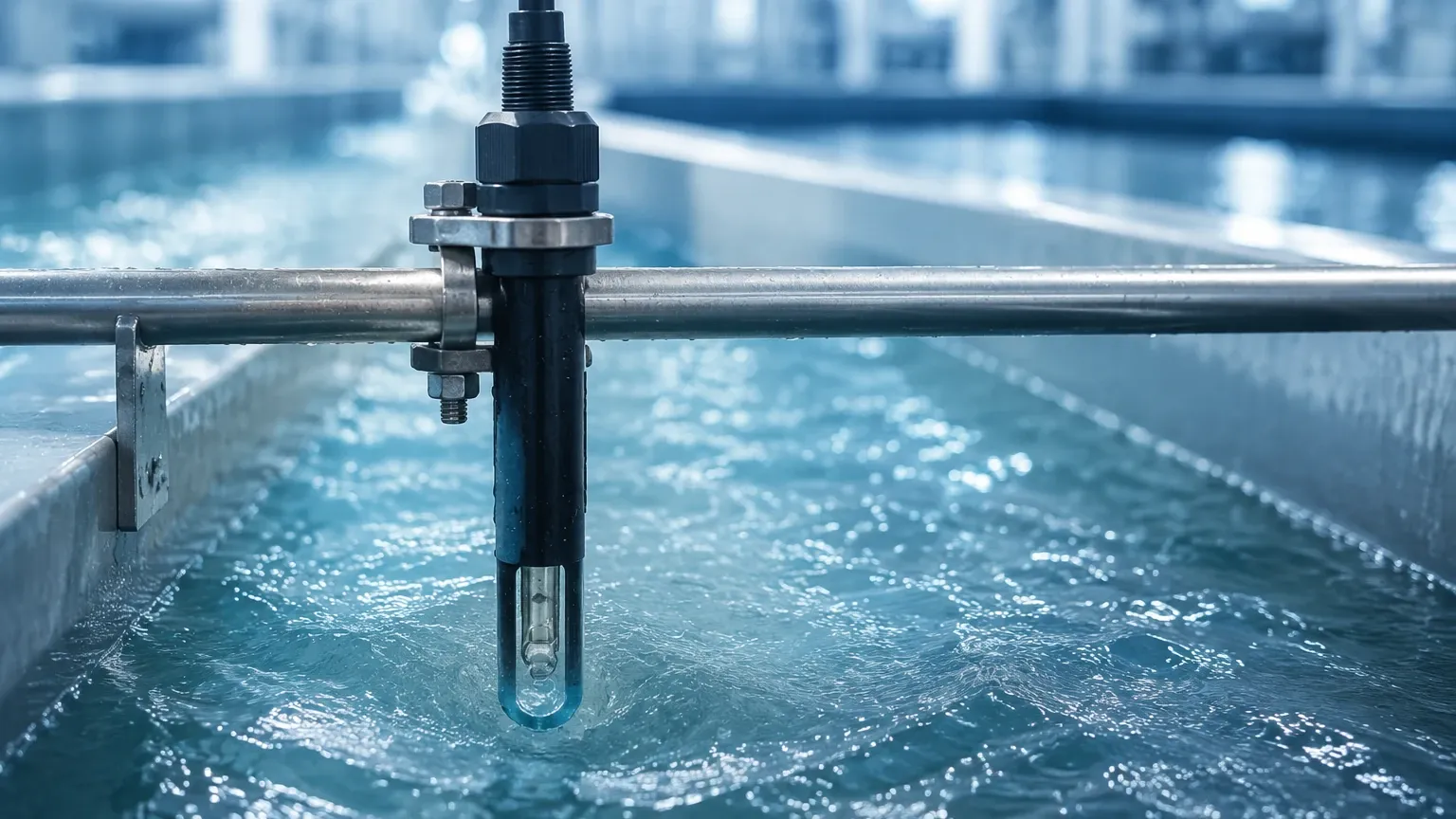
In B2B industrial settings, downtime is costly. Installing a pH sensor via a retractable housing (manual or pneumatic) allows the sensor to be removed for cleaning and calibration without shutting down the entire process line. This is particularly useful in applications where the sensor requires weekly maintenance due to heavy fouling.
Maintenance, Calibration, and Troubleshooting
Inline pH sensors are consumable items; their sensitivity degrades over time due to the chemical environment and the natural aging of the glass.
Calibration Protocols
Calibration should be performed using at least two buffer solutions (typically pH 4.0, 7.0, or 10.0) that bracket the expected process value.
* Zero Point (Offset): Usually calibrated at pH 7.0. The theoretical output is 0 mV. An offset of ±30 mV often indicates that the sensor needs cleaning or is nearing the end of its life.
* Slope (Efficiency): Calibrated using a second buffer. The slope should be between 90% and 105% of the theoretical 59.16 mV/pH. A slope below 85% usually necessitates sensor replacement.
Cleaning Procedures
Fouling is the most common cause of measurement error. The cleaning agent depends on the contaminant:
* Scaling/Mineral Deposits: 5% Hydrochloric acid (HCl).
* Oils and Greases: Mild detergent or isopropyl alcohol.
* Proteins: Acidic pepsin solution.
Limitations and Common Risks
While highly effective, inline pH sensors have inherent limitations that engineers must account for in their system design:
1. Dehydration: If the process line is drained and the sensor is left dry, the hydrated layer on the glass bulb will collapse. This leads to slow response times and eventual sensor failure. If a line is frequently empty, a U-trap or a bypass loop should be used to keep the sensor submerged.
2. High Resistance: At very low temperatures, the electrical resistance of the glass membrane increases exponentially, leading to sluggish response and susceptibility to electronic noise.
3. Alkaline Error: In very high pH environments (pH >12) with high sodium concentrations, the sensor may respond to sodium ions as if they were hydrogen ions, resulting in a reading that is lower than the actual pH. Special "low sodium error" glass should be specified for these conditions.
4. Pressure Fluctuations: Rapid changes in process pressure can force process fluid into the reference junction, contaminating the electrolyte. This is mitigated by using pressurized reference systems or solid electrolytes.
Integration with Process Control Systems
pH measurement rarely exists in isolation. In industrial automation, it is often integrated with level measurement to manage chemical dosing in tanks. For example, in a neutralization tank, a hydrostatic or ultrasonic level transmitter (technologies provided by manufacturers like Welk) ensures the tank does not overflow, while the inline pH sensor controls the pumps that add acid or caustic to reach the target pH.
Modern digital sensors (such as those using Memosens or similar protocols) convert the analog millivolt signal into a digital signal within the sensor head itself. This eliminates the risk of signal interference from nearby motors or power lines and allows for advanced diagnostics, such as "time in operation" and "highest temperature reached," to be stored directly on the sensor.
Frequently Asked Questions (FAQs)
Q: How often should I calibrate my inline pH sensor?
A: Frequency depends on the process. In clean water, monthly calibration may suffice. In aggressive chemical processes or wastewater, weekly or even daily checks may be required to maintain accuracy.
Q: Can I use a standard lab pH sensor for inline measurement?
A: No. Laboratory sensors are not designed to withstand process pressures, temperatures, or the mechanical stresses of flowing pipes. They lack the robust junctions and reinforced bodies necessary for industrial service.
Q: What is the typical lifespan of an industrial inline pH sensor?
A: In mild conditions, a sensor may last 12 to 24 months. In harsh chemical applications or high temperatures, the lifespan may be reduced to 3 to 6 months.
Q: Why is my pH reading drifting even after calibration?
A: Drifting is often caused by a clogged reference junction or a contaminated electrolyte. If cleaning the junction does not resolve the issue, the sensor likely needs replacement. It can also be caused by improper grounding of the piping system, creating "ground loops."
By following these engineering principles and selection guidelines, facilities can ensure that their liquid analysis remains as accurate and reliable as their level and pressure measurements, leading to optimized chemical usage and improved product quality.