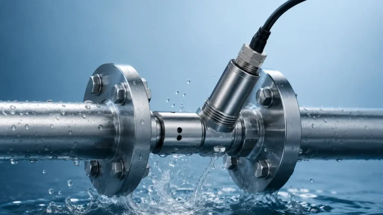
Level Measuring Devices
Level Measuring Devices
In modern industrial automation, the ability to accurately monitor the volume or height of materials within a vessel is fundamental to operational efficiency, safety, and inventory management. Level measuring devices serve as the sensory organs of a plant, providing real-time data for processes ranging from simple water storage to complex chemical reactions. Choosing the correct technology requires a deep understanding of both the physics of measurement and the specific characteristics of the medium being measured.
Industrial applications in water treatment, oil and gas, and chemical processing demand high reliability. Whether managing liquid chemicals, wastewater, or granular solids, selecting an appropriate instrument prevents overflows, protects pumps from dry running, and ensures precise dosing. This guide explores the primary measurement principles, selection criteria, and installation considerations for engineers and procurement professionals.
Understanding Measurement Principles
Before selecting a device, it is essential to understand how different technologies interact with the process media. Level measurement is generally categorized into two types: point level detection and continuous level measurement. Point level detection indicates whether a material has reached a specific height (high or low alarms), while continuous measurement provides a constant signal representing the exact level throughout the vessel's range.
Radar Level Measurement
Radar level meters utilize electromagnetic waves to determine the distance to the surface of the medium. There are two primary types: Guided Wave Radar (GWR) and Non-Contact Radar.
* Non-Contact Radar: These devices emit a high-frequency signal (typically 26GHz or 80GHz) from an antenna. The signal reflects off the material surface and returns to the sensor. The time-of-flight or frequency shift is used to calculate the distance. High-frequency 80GHz radar is particularly effective in narrow tanks or vessels with internal obstructions because it produces a narrow beam angle.
* Guided Wave Radar (GWR): This technology uses a probe (cable or rod) to guide the microwave pulse to the surface. It is highly effective for low dielectric constant liquids and applications with heavy foam or turbulence, as the probe concentrates the signal energy.
Ultrasonic Level Measurement
Ultrasonic sensors function by emitting high-frequency sound waves. These waves travel through the air, bounce off the liquid or solid surface, and return to the transducer. The device calculates the level based on the time elapsed and the speed of sound.
Because the speed of sound is influenced by air temperature, most high-quality ultrasonic level measuring devices include integrated temperature compensation. This technology is popular in water treatment and open-channel flow measurement due to its cost-effectiveness and non-contact nature. However, it is limited in vacuum conditions or high-pressure environments where sound cannot travel effectively.
Hydrostatic Level Measurement
Hydrostatic transmitters measure the pressure exerted by a liquid column at the bottom of a tank. Based on the principle that pressure is proportional to the height of the liquid and its density ($P = \rho gh$), the sensor converts the pressure reading into a level signal.
This method is highly reliable for vented tanks. In pressurized vessels, a differential pressure (DP) transmitter is used to subtract the headspace pressure from the total pressure at the bottom. Hydrostatic sensors are often submersible or flange-mounted and are preferred for their robustness in deep wells and large reservoirs.
Magnetic Level Gauges
Magnetic level gauges are used for visual indication and can be equipped with transmitters for remote monitoring. They consist of a bypass chamber connected to the vessel. Inside the chamber, a float containing a high-intensity magnet moves with the liquid level. Outside the chamber, a series of magnetic flags or a sensing element tracks the float's movement. This provides a clear, high-visibility mechanical display that requires no power for local indication, making it ideal for high-temperature and high-pressure chemical applications.
Technical Comparison and Selection Matrix
Selecting the right level measuring devices depends on the physical properties of the medium and the vessel's environment. The following table provides a general comparison of common technologies used in industrial automation.
| Technology | Typical Accuracy | Max Range | Media Type | Key Advantage |
| :— | :— | :— | :— | :— |
| Radar (80GHz) | ±1 mm | Up to 120 m | Liquids/Solids | Unaffected by dust, vapor, or pressure. |
| Ultrasonic | ±0.25% of range | Up to 30 m | Liquids/Slurries | Cost-effective, non-contact for water. |
| Hydrostatic | ±0.1% to 0.5% | Up to 200 m | Liquids | Simple installation, ideal for deep wells. |
| Guided Wave Radar | ±2 mm | Up to 75 m | Liquids/Solids | Excellent for low dielectric fluids. |
| Magnetic Gauge | ±5 mm (Visual) | Up to 6 m+ | Liquids | Safe visual indication for hazardous media. |
| Capacitance | ±0.5% to 1% | Up to 10 m | Liquids/Solids | Works well in high-temperature/pressure. |
Engineering Installation Guidelines
Even the most advanced level measuring devices will fail to provide accurate data if installed incorrectly. Engineers must consider several physical factors during the design phase.
1. Dead Zones (Blocking Distance): Every non-contact sensor has a "dead zone" or "blind zone" near the face of the transducer where it cannot accurately measure. For ultrasonic sensors, this might be 0.2 m to 0.8 m. For radar, it is typically much smaller (e.g., 50 mm). The device must be mounted high enough so that the maximum liquid level never enters this zone.
2. Nozzle Geometry: The mounting nozzle should be short and wide enough to prevent the signal from reflecting off the nozzle walls before it reaches the tank. For 80GHz radar, nozzle interference is minimized due to the narrow beam, but for ultrasonic sensors, the nozzle inner diameter must be carefully checked.
3. Internal Obstructions: Agitators, ladders, and heating coils can create false echoes. While modern software allows for "false echo suppression" or "background masking," it is best practice to install the sensor in a location with a clear line of sight to the material surface.
4. Stilling Wells and Bypass Chambers: In applications with heavy turbulence, foam, or boiling surfaces, installing the sensor inside a stilling well or a bypass pipe can provide a calm surface for more accurate measurement.
5. Environmental Protection: For outdoor installations, sunshields are recommended to prevent temperature fluctuations from affecting the electronics or the speed of sound calculations in ultrasonic units.

Common Risks and Limitations
While level measuring devices are highly versatile, certain conditions can compromise their performance:
* Vapor and Condensation: While radar is largely unaffected by vapor, ultrasonic signals can be attenuated by heavy steam or gas layers. Condensation on an ultrasonic transducer face can cause "ringing," leading to loss of signal. Radar units with PTFE-coated antennas are better suited for condensing environments.
* Foam: Heavy, thick foam can absorb ultrasonic and radar signals. Guided Wave Radar or hydrostatic transmitters are generally more reliable when thick foam is present.
* Density Fluctuations: Hydrostatic measurement relies on a constant liquid density. If the temperature of the liquid changes significantly, or if different chemicals are mixed, the density changes, leading to inaccuracies unless a density-compensated system is used.
* Dust and Build-up: In solid silos, heavy dust during filling can block ultrasonic signals. High-frequency radar is the industry standard for dusty environments because microwaves penetrate dust clouds easily.
FAQ: Frequently Asked Questions
Q: Can I use an ultrasonic sensor for vacuum tanks?
No. Sound waves require a medium (air or gas) to travel. In a vacuum, ultrasonic level measuring devices cannot function. Radar is the preferred choice for vacuum applications.
Q: How does the dielectric constant (DK) affect radar measurement?
The dielectric constant reflects how much of the radar signal is reflected back to the sensor. Water has a high DK (~80) and is easy to measure. Hydrocarbons like oil have low DK values (~2), which return a weaker signal. Guided Wave Radar is often required for materials with a DK below 1.5.
Q: What is the maintenance requirement for these devices?
Non-contact devices (Radar, Ultrasonic) generally require very little maintenance as they do not touch the media. Hydrostatic sensors may require periodic cleaning of the diaphragm if the liquid is prone to scaling or coating. Magnetic level gauges should be flushed periodically to prevent sediment build-up in the chamber.
Conclusion
Selecting the right level measuring devices is a balance between technical requirements and budget constraints. For critical process control, radar offers the highest precision and reliability across diverse conditions. For simpler water management, ultrasonic or hydrostatic sensors provide excellent value.
Before finalizing a specification, engineers should confirm the chemical compatibility of the wetted parts, the maximum process temperature and pressure, and the specific geometry of the vessel. For a comprehensive range of industrial solutions and technical support, you can visit the Main Page to explore specific product configurations tailored to your industry. Reliable measurement starts with choosing a partner that understands the nuances of industrial automation and provides the necessary OEM/ODM customization for unique application challenges.