Liquid Flow Control
Liquid Flow Control
In modern industrial processing, liquid flow control is a fundamental requirement for ensuring operational efficiency, safety, and product consistency. Whether managing the distribution of chemicals, treating wastewater, or overseeing oil and gas transport, the ability to regulate the movement of fluids depends heavily on the precision of measurement instrumentation. Effective control is rarely a standalone process; it is an integrated system where level measurement and flow regulation work in tandem to maintain mass balance and process stability.
For engineers and plant managers, selecting the right instrumentation requires a deep understanding of the physical principles governing fluid dynamics and the specific environmental challenges of the application. As a professional manufacturer, Welk provides a range of solutions—from radar level meters to hydrostatic transmitters—designed to facilitate precise liquid flow control across diverse industrial landscapes.
Fundamental Principles of Liquid Flow Control
Liquid flow control refers to the process of managing the rate, volume, and direction of fluid movement within a closed or open system. This is typically achieved through a feedback loop involving a primary sensing element (the meter), a controller (such as a PLC or DCS), and a final control element (such as a valve or pump).
The Role of Level Measurement in Flow Control
While flow meters measure the velocity or volume of liquid passing through a point, level sensors are often the primary tool for flow control in specific scenarios, such as open channel flow or tank inventory management.
1. Open Channel Flow: In wastewater treatment or irrigation, flow is often measured in flumes or weirs. By measuring the liquid level (head) at a specific point, the flow rate can be calculated using established hydraulic formulas (e.g., the Manning equation).
2. Inventory-Based Control: In batch processing, flow control is dictated by the level within a vessel. When a tank reaches a high-level setpoint, the flow control system must throttle or shut off the inlet to prevent overflow.
3. Hydrostatic Pressure: In many pressurized systems, the flow rate is a function of the pressure head. Hydrostatic level transmitters provide the data necessary to adjust pump speeds to maintain a constant flow rate despite changes in supply tank levels.
Level Measurement Technologies for Flow Applications
To achieve reliable liquid flow control, the measurement principle must align with the chemical and physical properties of the media. Below are the primary technologies utilized in industrial environments.
Radar Level Meters (Non-Contact)
Radar technology uses Time of Flight (ToF) principles. The sensor emits high-frequency microwave pulses that reflect off the liquid surface and return to the antenna. The time taken is proportional to the distance.
* Advantages: Highly accurate (often within ±2 mm), unaffected by temperature, pressure, or vacuum.
* Application: Ideal for volatile chemicals or high-temperature liquids where contact with the sensor is undesirable.
Ultrasonic Level Sensors (Non-Contact)
Ultrasonic sensors emit sound waves that bounce off the liquid surface. Like radar, they use ToF to determine the level.
* Advantages: Cost-effective and easy to install.
* Application: Frequently used in water treatment for open channel liquid flow control in flumes and weirs.
Hydrostatic Level Transmitters (Contact)
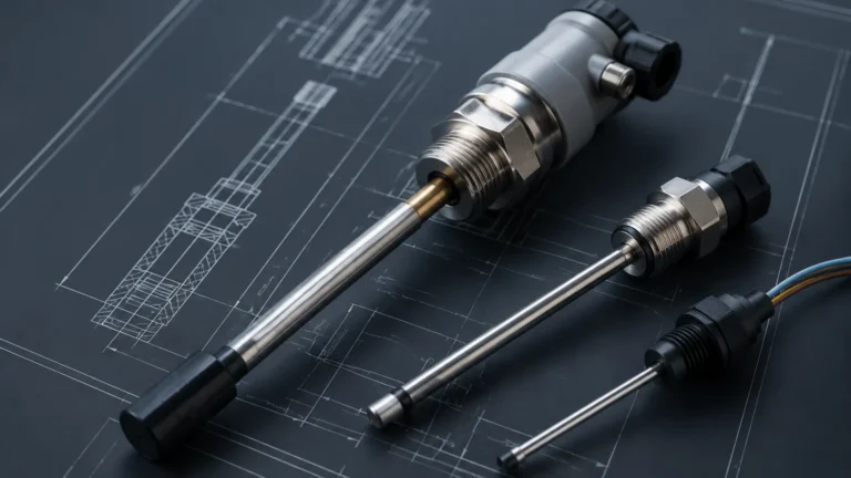
These sensors measure the pressure exerted by a liquid column. Since pressure is directly proportional to the height of the liquid and its density ($P = \rho gh$), the level can be calculated precisely.
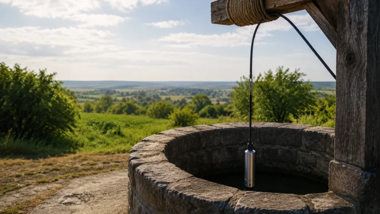
* Advantages: Excellent for deep wells, reservoirs, and vented tanks.
* Application: Used where surface foam or turbulence might interfere with non-contact sensors.
Magnetic Level Gauges and Switches
For visual confirmation and point-level control, magnetic gauges use a float equipped with a magnet to actuate external flags or switches.
* Application: Critical for safety redundancy in boiler drums or oil-water separators.
Engineering Selection Criteria for Flow Control Systems
Choosing the correct instrument for liquid flow control involves evaluating several technical parameters. The following table provides a comparison of common technologies based on typical industrial requirements.
| Feature | Radar Level Meters | Ultrasonic Sensors | Hydrostatic Transmitters | Magnetic Gauges |
| :— | :— | :— | :— | :— |
| Accuracy | High (±2 mm to ±5 mm) | Moderate (±0.25% of range) | Moderate (±0.1% to ±0.5%) | N/A (Visual/Point) |
| Media Type | Corrosive, viscous, clean | Water, wastewater, acids | Clean liquids, sludges | Clean or dirty liquids |
| Max Temperature | Up to +450°C | Up to +80°C | Up to +100°C | Up to +400°C |
| Max Pressure | Up to 160 bar | Up to 3 bar | Up to 40 bar | Up to 200 bar |
| Influence of Foam | Minimal (High freq) | Significant | None | None |
| Maintenance | Very Low | Low | Moderate (Cleaning) | Low |
Media Characteristics
Before finalizing a selection, confirm the liquid's dielectric constant (for radar), density (for hydrostatic), and viscosity. For example, a hydrostatic transmitter may require recalibration if the liquid density changes significantly due to temperature fluctuations, whereas a radar meter remains unaffected by density shifts.
Environmental Conditions
In outdoor applications, such as reservoir management, ultrasonic sensors must account for air temperature changes, which affect the speed of sound. Most modern ultrasonic units include integrated temperature compensation. For hazardous areas, ensure the device carries the appropriate ATEX or IECEx certifications.
Installation Guidelines and Best Practices
Proper installation is as critical as the choice of technology. Even the most advanced sensor will fail to provide accurate liquid flow control if it is poorly positioned.
1. Avoid the "Dead Zone": All ToF sensors (radar and ultrasonic) have a blocking distance or dead zone directly beneath the sensor where measurements are impossible. Ensure the maximum liquid level never enters this zone.
2. Nozzle Considerations: For radar and ultrasonic units, the sensor should be mounted away from the tank wall to avoid false reflections. If mounting on a nozzle, the nozzle's internal diameter and height must allow the signal beam to clear the bottom edge without interference.
3. Turbulence and Agitators: If the liquid surface is turbulent due to an agitator or high-velocity inlet, consider using a stilling well or a bypass pipe. This stabilizes the surface for the sensor, ensuring a steady signal for the control loop.
4. Alignment: For open channel flow, the sensor must be perfectly perpendicular to the liquid surface. A deviation of even a few degrees can result in signal loss or significant measurement error.
Addressing Operational Risks and Limitations
While industrial level and flow instruments are robust, they are not immune to environmental challenges. Understanding these limitations is key to maintaining a reliable liquid flow control system.
* Foam and Vapor: Heavy foam can absorb ultrasonic sound waves or scatter radar signals. In such cases, high-frequency radar (80 GHz) or contact-based hydrostatic sensors are preferred.
* Build-up and Scaling: In wastewater or chemical crystallization processes, material can build up on the sensor face. Non-contact sensors are generally better here, but they still require periodic inspection to ensure the face remains clear.
* Signal Interference: In metal tanks, internal structures like ladders or heating coils can create "ghost" echoes. Advanced software in modern meters allows for "false echo suppression," where the device is programmed to ignore static reflections.
Frequently Asked Questions (FAQ)
Q: How does temperature affect liquid flow control accuracy?
A: Temperature affects the density of the liquid and, in the case of ultrasonic sensors, the speed of sound. If using hydrostatic sensors, a temperature-induced density change will result in a level error unless compensated. Radar is generally immune to temperature variations in the vapor space.
Q: Can I use one sensor for both level and flow?
A: Yes, in open channel applications (like a Parshall flume), a single ultrasonic or radar level sensor can calculate the flow rate based on the height of the liquid. The controller converts the level measurement into a flow volume per unit of time.
Q: What is the benefit of a 4-20mA HART output in flow control?
A: The 4-20mA signal is the industry standard for analog control, while the HART protocol allows for digital communication. This enables remote configuration, diagnostics, and the transmission of multiple variables (e.g., level and temperature) over a single pair of wires.
Conclusion: Moving Toward Implementation
Successful liquid flow control requires a holistic view of the process environment. Before proceeding with a project, technical teams should confirm the chemical compatibility of the wetted parts, the required measurement range, and the integration requirements with existing control hardware.
For those seeking to optimize their process loops with high-performance instrumentation, it is essential to partner with a manufacturer that offers both technical expertise and a diverse product portfolio. To explore specific instrument specifications and engineering data, you can Review product options and application support on our Main Page to find the ideal solution for your facility's requirements. By focusing on factual measurement data and adhering to rigorous installation standards, industrial operators can achieve a level of flow control that enhances both safety and profitability.