Liquid Level Control Relay
Liquid Level Control Relay
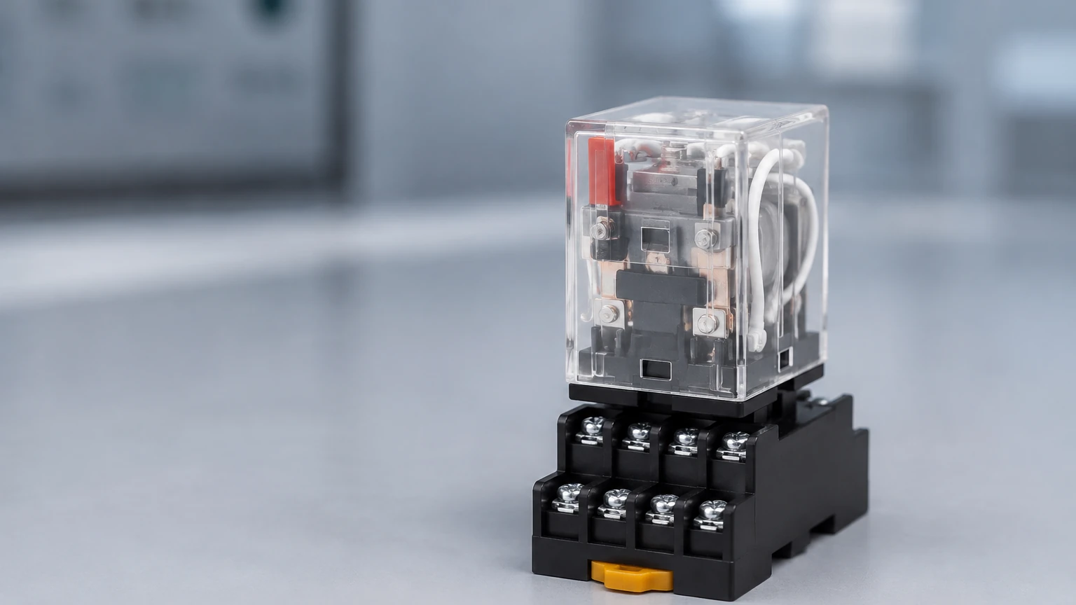
In the landscape of industrial automation and process control, the liquid level control relay serves as a critical bridge between physical fluid states and electrical control systems. These devices are engineered to monitor the level of liquids within tanks, wells, or reservoirs and automatically initiate actions—such as starting a pump, opening a valve, or triggering an alarm—when specific thresholds are reached. For engineers and facility managers, selecting the correct relay is essential for preventing dry-running of pumps, avoiding tank overflows, and maintaining consistent process variables.
Measurement Principles and Operational Logic
To effectively integrate a liquid level control relay into a system, one must first understand the underlying measurement principles that trigger the relay’s internal switching mechanism. While the term "relay" often refers to the electronic module mounted in a control panel, its operation is inextricably linked to the sensing technology deployed in the fluid.
Conductive Sensing Principle
Most dedicated liquid level control relays operate on the principle of conductivity. This method utilizes the electrical resistance of the liquid itself. Probes (electrodes) are suspended in the tank at specific heights. When the liquid rises and touches an electrode, a low-voltage electrical circuit is completed through the liquid to a common ground or a reference probe. The relay detects this change in resistance and switches its output contacts.
This principle requires the liquid to be electrically conductive (typically >5 μS/cm). It is highly effective for water, wastewater, and many chemical solutions, but it is unsuitable for non-conductive fluids like oils, pure deionized water, or hydrocarbons.
Signal-Based Control (4-20mA Integration)
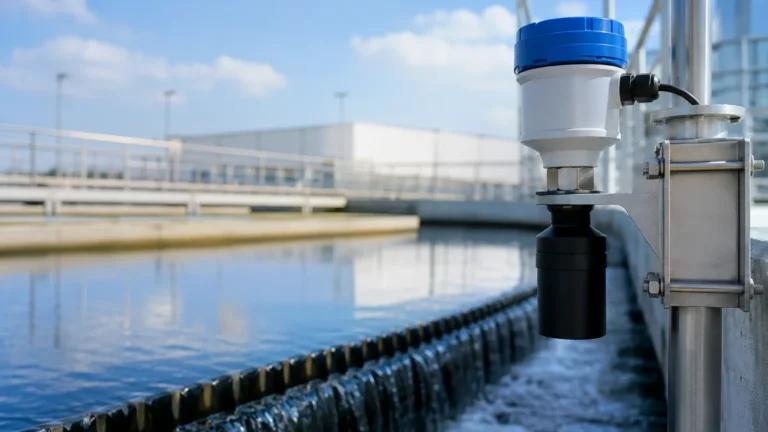
In more complex industrial environments, the relay functions as a setpoint controller. Instead of direct electrode inputs, the relay receives a standardized analog signal (typically 4-20mA) from a primary transmitter, such as a radar level meter or an ultrasonic sensor. The relay is programmed with high and low setpoints. When the incoming signal reaches these values, the relay toggles. This approach is common in applications where continuous monitoring is required alongside discrete control actions. For a comprehensive overview of the primary sensors that provide these signals, engineers can refer to the Main Page of industrial measurement solutions.
Key Evaluation Criteria for Selection
Selecting a liquid level control relay requires a detailed assessment of both the electrical requirements and the physical properties of the application. Failure to match the relay to the environment can lead to premature component failure or unsafe process conditions.
1. Sensitivity Adjustment: Different liquids have varying levels of conductivity. A relay used for sewage (high conductivity) requires different sensitivity settings than one used for distilled water (low conductivity). Modern relays often feature an adjustable sensitivity range, typically measured in kilo-ohms (kΩ).
2. Contact Rating and Configuration: The relay's output contacts must be rated for the load they are switching. Common configurations include Single Pole Double Throw (SPDT) or Double Throw (DPDT). If the relay is directly controlling a high-horsepower pump motor, an intermediate motor starter or contactor must be used to protect the relay from high inrush currents.
3. Operating Voltage: Relays are available in various supply voltages, including 24V DC for control circuits and 110V/230V AC for general industrial use. Ensuring compatibility with the existing control panel power supply is a fundamental step.
4. Hysteresis and Time Delay: To prevent "chatter" (rapid switching caused by surface turbulence or waves), quality relays include adjustable time delays and built-in hysteresis. This ensures the pump stays on or off until the level has definitively moved past the setpoint.
Practical Selection Table
The following table compares common types of liquid level control relay configurations based on typical industrial needs:
| Feature | Conductive Relay (Electrode) | Float-Actuated Relay | Digital Setpoint Controller |
| :— | :— | :— | :— |
| Primary Application | Conductive liquids, sump control | Non-conductive liquids, simple tanks | Precision process control, chemical tanks |
| Liquid Compatibility | Water, acids, bases (must be conductive) | Oils, fuels, water | All (depends on external sensor) |
| Moving Parts | None | Mechanical float | None |
| Installation Complexity | Moderate (requires probe mounting) | Simple (mechanical mounting) | High (requires sensor + programming) |
| Maintenance | Periodic cleaning of probes | High (cleaning of mechanical parts) | Low (solid-state electronics) |
| Typical Output | SPDT/DPDT Relay | Microswitch | Relay + 4-20mA Retransmission |
Installation Considerations and Best Practices
Correct installation is paramount to the reliability of a liquid level control relay system. Engineers should adhere to the following guidelines to ensure long-term performance:
* Probe Placement: In conductive systems, probes should be installed away from the tank's inlet to avoid false triggering caused by splashing liquid. If the tank is made of non-conductive material (like plastic or fiberglass), a reference "common" probe must be installed that reaches the lowest point in the tank.
* Wiring Separation: Signal wires from the probes or sensors to the relay should be kept separate from high-voltage power lines to prevent electromagnetic interference (EMI). Using shielded cables is recommended for long distances (over 50 meters).
* Mounting Environment: Most industrial relays are designed for DIN rail mounting inside a protected NEMA or IP-rated enclosure. Ensure the ambient temperature within the cabinet does not exceed the relay's operating limit, typically around 55°C to 60°C.
* Grounding: Proper grounding of the system is essential, especially for conductive relays, to ensure a stable return path for the detection current and to protect the electronics from surges.
Limitations and Common Risks
While liquid level control relays are robust, they are not universal solutions. Understanding their limitations prevents operational failures:
* Scaling and Coating: In applications involving wastewater or lime slurries, electrodes can become coated with non-conductive debris or scale. This increases resistance and may prevent the relay from detecting the liquid level. Regular maintenance and the use of "self-cleaning" or shrouded probes can mitigate this.
* Electrolysis: If a DC voltage is used across the probes in a conductive system, electrolysis can occur, leading to probe erosion and liquid contamination. High-quality relays use an AC signal for probe detection to prevent this electrochemical reaction.
* Vapor and Foam: In tanks with heavy foaming, a conductive relay may trigger prematurely as the foam completes the circuit. In such cases, a different technology, such as a radar level meter with foam-suppression logic, should be used to feed the relay signal.
* Hazardous Areas: For applications involving flammable liquids or explosive atmospheres, intrinsically safe relays must be used. These limit the energy sent to the probes to levels that cannot ignite the atmosphere.
Frequently Asked Questions (FAQ)
Q: Can a liquid level control relay be used for oil?
A: Standard conductive relays cannot be used for oil because oil is non-conductive. For oil level control, a relay that interfaces with a float switch, ultrasonic sensor, or capacitive probe is required.
Q: How far can the relay be located from the tank?
A: This depends on the sensitivity of the relay and the cable capacitance. Generally, distances up to 100 meters are achievable with shielded cable, but high-sensitivity settings may be affected by long cable runs.
Q: What is the difference between "Fill" and "Drain" modes?
A: In "Drain" mode (Down control), the relay turns on the pump when the level is high and off when it is low. In "Fill" mode (Up control), the relay turns on the pump when the level is low and off when it is high. Most industrial relays have a switch to select between these two logics.
Q: Do I need a separate relay for every tank?
A: Yes, typically one relay module is required per control loop. However, some multi-channel relays can monitor multiple levels or multiple tanks within a single housing to save space in the control panel.
Conclusion
The liquid level control relay remains a fundamental component in industrial fluid management. By providing a reliable interface between level detection and pump/valve actuation, it ensures process continuity and equipment safety. When selecting a relay, engineers must balance the conductivity of the medium, the required electrical output, and the environmental conditions of the installation. For those integrating these relays into broader automation frameworks, exploring the full range of primary sensing technologies—from radar to hydrostatic transmitters—is the next logical step in optimizing process efficiency. Detailed specifications on these primary sensors can be found by reviewing the equipment options available on the Main Page of professional level measurement providers.