Liquid Level Sensing
Liquid Level Sensing
Liquid level sensing is a fundamental requirement in modern industrial process control, serving as the backbone for inventory management, process safety, and operational efficiency. In sectors ranging from water treatment and chemical processing to oil and gas and industrial automation, the ability to accurately monitor the volume of liquids in tanks, silos, and open channels is critical.
Welk, as a professional manufacturer of industrial level measurement instruments, provides a comprehensive suite of technologies designed to meet these diverse needs. Understanding the underlying physical principles of liquid level sensing is the first step for any engineer or facility manager in selecting the most appropriate instrumentation for their specific application. This guide explores the primary measurement technologies, their selection criteria, and practical installation considerations to ensure long-term reliability.
Principles of Liquid Level Sensing Technologies
Before selecting a sensor, it is essential to understand how different technologies interact with the liquid media and the environment. Liquid level sensing can be broadly categorized into continuous measurement and point level detection.
1. Radar Level Measurement
Radar technology is widely considered the gold standard for high-precision liquid level sensing. It operates on the principle of electromagnetic wave propagation. There are two primary types: non-contact radar and guided wave radar (GWR).
* Non-Contact Radar: These sensors emit high-frequency microwave pulses (typically at 26GHz or 80GHz) toward the liquid surface. The waves reflect off the surface and return to the sensor. The device measures the time-of-flight to calculate the distance. The 80GHz frequency is particularly effective due to its narrow beam angle, which allows it to avoid internal tank obstructions like agitators or heating coils.
* Guided Wave Radar (GWR): This method uses a physical probe (rod or cable) to guide the microwave pulse directly to the liquid surface. This is highly effective for liquids with low dielectric constants or in applications with heavy foam and turbulence, as the probe concentrates the signal energy.
2. Ultrasonic Level Sensing
Ultrasonic sensors utilize sound waves rather than electromagnetic waves. The sensor transmits an ultrasonic pulse that travels through the air, reflects off the liquid surface, and returns to the transducer.
Because sound velocity is affected by air temperature, most ultrasonic sensors include an integrated temperature sensor to compensate for changes in the speed of sound. This technology is cost-effective and ideal for water and wastewater applications, but it has limitations in high-pressure environments or where heavy vapors and foam can absorb or scatter the sound waves.
3. Hydrostatic Level Measurement
Hydrostatic sensing is based on the principle that the pressure at the bottom of a liquid column is directly proportional to the height of the liquid above it, governed by the formula: $P = \rho gh$ (where $P$ is pressure, $\rho$ is liquid density, $g$ is gravity, and $h$ is the height of the liquid).
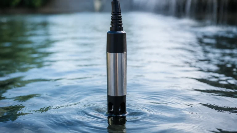
These sensors are typically submersible transmitters or pressure transducers mounted at the bottom of a tank. They are highly reliable for vented tanks where the liquid density remains constant. However, if the tank is pressurized, a differential pressure (DP) transmitter is required to subtract the top-side gas pressure from the total bottom pressure.
4. Magnetic Level Gauges
Magnetic level sensing involves a float containing a permanent magnet that moves up and down a bypass chamber connected to the process vessel. As the float moves with the liquid level, the magnet flips colored flaps or activates a reed-chain transmitter mounted outside the chamber. This provides a clear visual indication and a continuous electrical signal without the sensor coming into direct contact with the process media.
Technical Selection Criteria
Choosing the right liquid level sensing technology requires a systematic evaluation of the process environment. The following table provides a quick reference for common technologies based on application variables.
| Technology | Accuracy | Media Type | Temp. Range | Pressure Range | Ideal Application |
| :— | :— | :— | :— | :— | :— |
| 80GHz Radar | ±1 mm | Corrosive, viscous, clean | -40 to +200°C | Up to 40 Bar | Chemical tanks, precision storage |
| Ultrasonic | ±0.25% FS | Water, wastewater | -40 to +80°C | Atmospheric | Open channels, sumps |
| Hydrostatic | ±0.2% FS | Clean liquids, oils | -20 to +80°C | Up to 100 Bar | Deep wells, water reservoirs |
| Guided Wave Radar | ±2 mm | Low dielectric, foam | -50 to +400°C | Up to 400 Bar | Oil/water interface, steam boilers |
| Magnetic Gauge | ±5 mm | Hazardous, high temp | -196 to +450°C | Up to 320 Bar | Boiler drums, fuel storage |
Media Properties
The physical and chemical characteristics of the liquid are the most significant factors. For example, radar sensors depend on the dielectric constant (Dk) of the liquid. If the Dk is too low (less than 1.4), the signal reflection may be too weak for standard non-contact radar, necessitating the use of Guided Wave Radar.
Process Conditions
Temperature and pressure fluctuations can eliminate certain technologies. Ultrasonic sensors generally fail above 80°C or in vacuum conditions because sound requires a medium (air) to travel. In contrast, radar operates effectively in vacuums and at temperatures exceeding 200°C.
Installation Considerations and Best Practices
Proper installation is as important as selecting the right sensor. Even the most advanced liquid level sensing instrument will provide inaccurate data if installed incorrectly.
1. Dead Zones (Blocking Distance): Every top-mounted sensor (Radar and Ultrasonic) has a "dead zone" directly beneath the transducer where measurements cannot be taken. Ensure the sensor is mounted high enough so that the maximum liquid level never enters this zone.
2. Nozzle Geometry: For radar and ultrasonic sensors, the mounting nozzle should be as short and wide as possible. If a nozzle is too narrow or too long, it can create internal reflections (ringing) that interfere with the signal from the liquid surface.
3. Avoid Obstructions: Sensors should not be mounted directly above inflow pipes, internal ladders, or agitator blades. If obstructions are unavoidable, use radar sensors with "false echo suppression" software to map out and ignore these static reflections.
4. Positioning: In tanks with domed tops, do not mount the sensor in the exact center. This can cause a "parabolic effect," where multiple reflections from the tank walls converge at the center, creating a false high signal. Positioning the sensor at 1/3 to 1/2 of the tank radius is generally recommended.
Limitations and Common Risks
While modern liquid level sensing is highly advanced, certain conditions present ongoing challenges:
* Heavy Foam: Foam can act as an insulator for ultrasonic waves and can significantly attenuate radar signals. In cases of dense, thick foam, Guided Wave Radar or Hydrostatic sensors are usually the safer choice.
* Build-up and Scaling: For contact-based methods like floats or GWR probes, the buildup of sticky or crystallizing media can cause the float to jam or the probe to give false readings. Non-contact radar is preferred for these "dirty" applications.
* Density Changes: Hydrostatic sensors are calibrated based on a specific liquid density. If the liquid density changes due to temperature fluctuations or mixing of different chemicals, the level reading will drift unless real-time density compensation is implemented.
Frequently Asked Questions (FAQs)
Q: How often do liquid level sensors need calibration?
A: This depends on the technology. Radar and ultrasonic sensors are generally "set and forget" once calibrated during commissioning, as they have no moving parts. Hydrostatic sensors may require annual zero-point checks to account for sensor drift.
Q: Can one sensor measure both the total level and the interface between two liquids?
A: Yes, Guided Wave Radar is specifically designed for this. It can detect the top of an upper liquid layer (like oil) and the interface between that layer and a lower liquid (like water), provided the upper layer has a lower dielectric constant.
Q: What is the maximum range for ultrasonic level sensing?
A: Most industrial ultrasonic sensors have a maximum range of 15 to 30 meters. For distances beyond this, or for more challenging environments, radar is typically required.
Conclusion
Effective liquid level sensing is a balance between understanding the physics of the measurement and the practical constraints of the industrial environment. By selecting the appropriate technology—whether it be the precision of 80GHz radar or the robust simplicity of hydrostatic pressure—operators can ensure safety and optimize their processes. For a detailed look at specific instrument specifications and to find the right fit for your facility, you can review product options and application support on our Main Page.
Welk continues to innovate in the field of industrial automation, providing reliable and cost-effective solutions for the world's most demanding level measurement challenges. Confirming your process temperature, pressure, and media characteristics before purchase will ensure that your sensing solution provides accurate data for years to come.