Magnetic Flow Measurement
Magnetic Flow Measurement
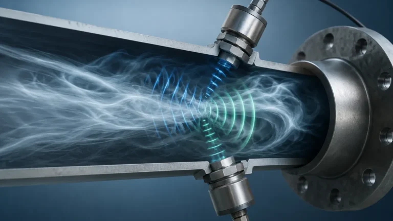
Magnetic flow measurement, often referred to as electromagnetic flow metering or "magmeter" technology, is a cornerstone of modern industrial process control. Based on the fundamental principles of physics, this method provides a non-invasive, highly accurate way to measure the volumetric flow rate of conductive liquids. Unlike mechanical flow meters, magnetic flow meters have no moving parts in the flow stream, which significantly reduces maintenance requirements and pressure drop across the instrument. For engineers and facility managers, understanding the nuances of magnetic flow measurement is essential for optimizing systems in water treatment, chemical processing, and industrial automation.
Principles of Magnetic Flow Measurement
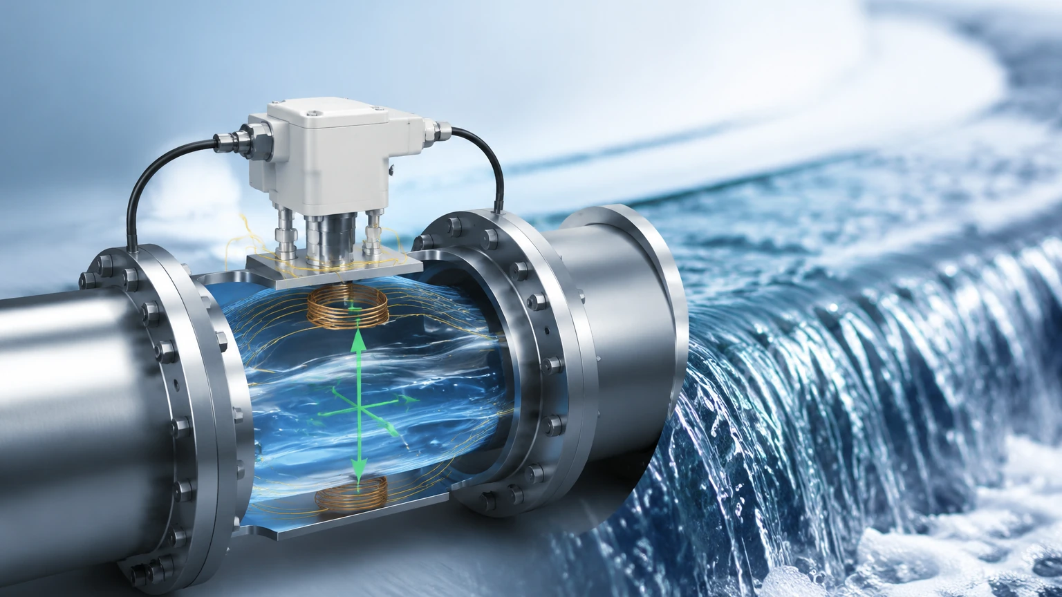
The operation of a magnetic flow meter is governed by Faraday’s Law of Electromagnetic Induction. This law states that a voltage is induced when a conductive medium moves through a magnetic field. In the context of a flow meter, the liquid acts as the conductor, and the meter’s internal coils generate the magnetic field.
Faraday’s Law in Practice
The relationship is expressed by the formula:
E = kBDv
Where:
* E is the induced voltage (the signal measured by the electrodes).
* k is a constant specific to the instrument.
* B is the strength of the magnetic field.
* D is the inner diameter of the pipe (the distance between electrodes).
* v is the average velocity of the liquid.
As the fluid flows through the pipe at a certain velocity (v), it passes through a magnetic field (B) generated by coils located outside the flow tube. The resulting voltage (E) is directly proportional to the velocity of the fluid. Because the cross-sectional area of the pipe (D) is known and constant, the transmitter can calculate the volumetric flow rate by multiplying the velocity by the area.
Crucially, this measurement is independent of fluid density, viscosity, temperature, and pressure, provided the fluid maintains a minimum level of electrical conductivity. This makes magnetic flow measurement exceptionally versatile for diverse industrial applications.
System Components and Construction
A magnetic flow measurement system consists of two primary parts: the primary device (the flow tube or sensor installed in the pipeline) and the secondary device (the transmitter or converter that processes the signal).
The Flow Tube
The flow tube is typically a non-magnetic stainless steel pipe section lined with an insulating material. The choice of liner is critical as it prevents the induced voltage from shorting out against the metal pipe. Common liner materials include:
* PTFE (Teflon): Excellent for high temperatures and aggressive chemicals.
* PFA: Similar to PTFE but with higher mechanical stability at elevated temperatures.
* Hard/Soft Rubber: Often used in water treatment and for abrasive slurries.
Electrodes
Two electrodes are mounted flush with the liner, positioned opposite each other. These electrodes pick up the induced voltage signal. Depending on the chemical nature of the fluid, electrodes may be constructed from 316L Stainless Steel, Hastelloy, Tantalum, or Platinum.
The Transmitter
The transmitter provides the excitation current to the coils to create the magnetic field and amplifies the microvolt-level signal from the electrodes. Modern transmitters provide digital displays and various output protocols, such as 4-20mA, HART, Modbus, or Profibus, allowing for seamless integration into a plant’s PLC or SCADA system.
Key Evaluation Criteria for Selection
When selecting a magnetic flow meter, several technical parameters must be evaluated to ensure long-term reliability and accuracy.
1. Fluid Conductivity
The most critical requirement for magnetic flow measurement is that the fluid must be electrically conductive. Most industrial magmeters require a minimum conductivity of 5 μS/cm (microsiemens per centimeter). While most water-based liquids and chemicals meet this threshold, hydrocarbons, oils, and deionized water typically do not and cannot be measured using this technology.
2. Flow Velocity and Pipe Size
Magmeters are sized based on flow velocity rather than the existing pipe size. For optimal accuracy, the velocity should generally fall between 0.5 m/s and 10 m/s (approx. 1.6 to 33 ft/s). If the existing pipe results in a velocity that is too low, a smaller meter with reducers may be necessary to increase the velocity through the sensor.
3. Chemical Compatibility
Both the liner and the electrodes must be compatible with the process fluid. For example, while 316L stainless steel is standard, it may corrode quickly in the presence of concentrated hydrochloric acid, necessitating the use of Tantalum electrodes.
4. Ambient and Process Conditions
Engineers must consider the maximum process temperature and pressure. High-pressure applications require specific flange ratings (e.g., PN40 or ANSI 300#), while high-temperature fluids may require a remote-mounted transmitter to protect the electronics from heat damage.
Selection Table: Liner and Electrode Materials
| Application | Recommended Liner | Recommended Electrode | Notes |
| :— | :— | :— | :— |
| Potable Water | EPDM / Hard Rubber | 316L Stainless Steel | Requires NSF/WRAS approvals for drinking water. |
| Wastewater / Sewage | Hard Rubber / Polyurethane | 316L / Hastelloy C | Polyurethane offers good abrasion resistance. |
| Corrosive Acids (HCl, H2SO4) | PTFE / PFA | Tantalum / Platinum | PFA is preferred for vacuum conditions. |
| Abrasive Slurries (Mining) | Ceramic / Thick Rubber | Tungsten Carbide | Ceramic liners offer the best wear resistance. |
| Food & Beverage | PFA / PTFE | 316L (Polished) | Requires Tri-clamp or hygienic connections. |
Installation Considerations
Proper installation is paramount to achieving the specified accuracy (typically ±0.5% of reading or better).
Straight Pipe Runs
To ensure a stable and symmetrical flow profile, magmeters require a certain amount of straight pipe upstream and downstream of the sensor. A common engineering standard is 5D upstream (five times the nominal pipe diameter) and 3D downstream. If valves or pumps are located immediately before the meter, longer upstream runs may be required to eliminate turbulence.
Pipe Orientation and Filling
The magnetic flow meter must always be full of liquid to measure accurately.
* Vertical Installation: The preferred orientation is vertical with the flow moving upward. This ensures the pipe remains full and prevents air bubbles from collecting at the electrodes.
* Horizontal Installation: If installed horizontally, the electrode axis must be horizontal (at the 3 o'clock and 9 o'clock positions). This prevents air bubbles at the top of the pipe or sediment at the bottom from interfering with the electrode signal.
Grounding
Because the induced voltage is very small, any stray electrical noise in the pipeline can cause significant measurement errors. Proper grounding is essential. This involves electrically bonding the flow meter to the process fluid using grounding rings or grounding electrodes, especially when the meter is installed in plastic or lined piping.
Limitations and Common Risks
While highly versatile, magnetic flow measurement is not a universal solution. Engineers should be aware of the following limitations:
1. Conductivity Requirements: As mentioned, non-conductive fluids like diesel, gasoline, or ultrapure water cannot be measured.
2. Gas Content: Large bubbles or high entrained gas content (above 5% by volume) can cause the signal to become unstable or lead to significant measurement errors.
3. Electrode Coating: In applications involving sticky or oily fluids, a film can build up on the electrodes over time, insulating them from the fluid and causing the meter to fail. Some advanced transmitters offer "electrode cleaning" or diagnostic functions to detect this.
4. Vacuum Conditions: Certain liners, particularly PTFE, can collapse or be pulled away from the flow tube wall under vacuum conditions. For applications involving vacuum, PFA liners with mechanical reinforcement are recommended.
Integration with Level Measurement
In many industrial processes, magnetic flow measurement works in tandem with level measurement technologies. For example, in a chemical dosing tank, a radar level meter monitors the volume of the reagent available, while a magmeter precisely controls the amount of reagent being pumped into the process.
Welk provides a comprehensive range of industrial instrumentation to support these integrated systems. While flow measurement handles the movement of fluids, our core expertise lies in providing reliable, accurate, and cost-effective level measurement solutions. For those designing complex automation systems, reviewing the Main Page for product options and application support ensures that both flow and level parameters are managed with high-precision instruments. Integrating these technologies allows for better mass balance calculations and improved safety in hazardous environments.
Frequently Asked Questions (FAQs)
Q: Can a magnetic flow meter measure the flow of steam or air?
A: No. Magnetic flow meters only work with conductive liquids. For gases or steam, technologies like vortex or thermal mass flow meters are required.
Q: Does the viscosity of the liquid affect the accuracy?
A: No. One of the primary advantages of magnetic flow measurement is that it is independent of viscosity and density, making it ideal for thick slurries or varying chemical concentrations.
Q: What happens if the pipe is only half full?
A: The meter will provide an inaccurate, usually higher-than-actual reading, or it may signal an error. The sensor must be completely full of liquid to function correctly.
Q: How often does a magmeter need calibration?
A: Because there are no moving parts to wear out, magmeters are very stable. In many water applications, calibration is only checked every 2–5 years, though critical chemical or custody transfer applications may require annual verification.
Conclusion
Magnetic flow measurement remains a preferred technology for industrial liquid flow due to its accuracy, lack of pressure drop, and low maintenance requirements. By carefully selecting the appropriate liner and electrode materials and adhering to strict installation guidelines—particularly regarding grounding and straight pipe runs—engineers can ensure reliable performance in even the most demanding environments. When combined with robust level measurement strategies, magnetic flow meters provide the data necessary for efficient, safe, and automated industrial operations.