Mass Flow Meter for Gas
Mass Flow Meter for Gas
In industrial process control, the accurate measurement of gas flow is a fundamental requirement for safety, efficiency, and cost accounting. Unlike liquids, which are largely incompressible, gases change volume significantly with fluctuations in temperature and pressure. This characteristic makes volumetric flow measurement inherently unreliable for gas unless complex compensation calculations are applied. Consequently, the industry has shifted toward the mass flow meter for gas, which measures the actual number of molecules passing through a pipe, regardless of environmental changes.
For engineers and plant managers, selecting the right instrumentation requires a deep understanding of measurement principles, gas properties, and installation constraints. This guide explores the technical landscape of gas mass flow measurement to assist in informed procurement and system design.
Understanding Mass Flow Measurement for Industrial Gases
To understand why mass flow is the preferred metric, one must consider the Ideal Gas Law ($PV = nRT$). In a volumetric system, if the pressure ($P$) doubles, the volume ($V$) of the gas is halved, even though the amount of substance ($n$) remains the same. If a process relies on a specific chemical reaction or energy output, the mass of the gas is the only variable that provides a consistent baseline.
There are two primary ways to determine mass flow:
1. Direct Mass Measurement: The instrument responds directly to the mass or inertia of the gas (e.g., Coriolis meters).
2. Inferred Mass Measurement: The instrument measures heat transfer (e.g., Thermal Dispersion) or uses multi-variable sensors to measure volume, temperature, and pressure simultaneously to calculate mass.
In modern industrial automation, integrating these flow readings with inventory data from level sensors—such as those provided by Welk—allows for a complete mass balance of the facility. For more information on integrated measurement solutions, you can visit our Main Page to review product options and application support.
Primary Measurement Principles
Thermal Dispersion Technology
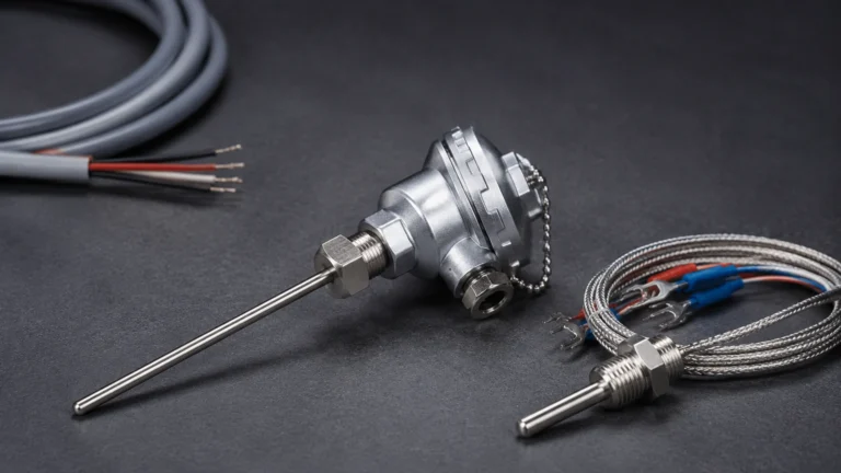
Thermal mass flow meters operate on the principle of convective heat transfer. The sensor typically consists of two Resistance Temperature Detectors (RTDs). One RTD acts as a reference, measuring the ambient temperature of the gas. The second RTD is heated to a specific, constant temperature differential above the reference.
As gas molecules flow past the heated sensor, they carry away heat. The instrument measures the amount of electrical power required to maintain the temperature differential. Since the cooling effect is directly proportional to the number of gas molecules (the mass) passing over the sensor, the meter can provide a direct mass flow reading. This technology is particularly effective for clean gases like Nitrogen ($N_2$), Compressed Air, and Argon ($Ar$).
Coriolis Principle
Coriolis meters utilize the inertia of the gas. The instrument contains one or more vibrating tubes. As gas flows through these tubes, the Coriolis effect causes the tubes to twist or shift in phase. Sensors at the inlet and outlet of the tubes detect this phase shift, which is directly proportional to the mass flow rate.
While Coriolis meters are highly accurate (often within ±0.5% of the rate), they are generally more expensive and introduce a higher pressure drop compared to thermal meters. They are most commonly used for high-value gases or applications where the gas composition is unknown or variable.
Selection Criteria for Gas Flow Instrumentation
When evaluating a mass flow meter for gas, several technical parameters must be confirmed before procurement. Selecting a meter based solely on pipe size is a common engineering error that leads to poor performance.
1. Gas Composition: Is the gas a single component or a mixture? Thermal meters are calibrated for specific gas properties (thermal conductivity). If the gas mixture changes, the calibration becomes invalid. Coriolis meters, conversely, are largely independent of gas composition.
2. Flow Range (Turndown Ratio): Thermal meters offer exceptional turndown ratios, often 100:1 or higher, making them ideal for detecting leaks or measuring varying demand in compressed air systems.
3. Accuracy and Repeatability: Determine if the process requires accuracy as a percentage of "Full Scale" (FS) or a percentage of "Reading." For custody transfer, high-accuracy Coriolis meters are standard.
4. Process Conditions: High-pressure applications (above 50 bar / 725 psi) or extreme temperatures (above 200°C / 392°F) may limit the use of certain sensor materials or electronics.
Technical Comparison and Selection Table
The following table provides a generalized comparison of common technologies used for measuring gas mass flow in industrial settings.
| Feature | Thermal Dispersion | Coriolis | Multivariable Differential Pressure (DP) |
| :— | :— | :— | :— |
| Measurement Type | Direct Mass | Direct Mass | Inferred (Compensated) |
| Accuracy (Typical) | ±1% FS to ±1% Reading | ±0.5% of Rate | ±1.0% to ±2.0% of Rate |
| Turndown Ratio | 100:1 | 20:1 to 50:1 | 10:1 |
| Pressure Drop | Negligible | Moderate to High | High (due to Orifice Plate) |
| Maintenance | Low (No moving parts) | Low | Moderate (Impulse lines) |
| Initial Cost | Moderate | High | Moderate |
| Best Application | Compressed Air, Vent Gas | Chemical Processing | Steam, High Velocity Gas |
Installation Guidelines and Best Practices
Even the most advanced mass flow meter for gas will fail to provide accurate data if installed incorrectly. Proper flow profile development is the most critical factor in installation.
Straight Pipe Runs
Most gas meters require a specific length of straight pipe upstream and downstream of the sensor to eliminate turbulence caused by elbows, valves, or reducers.
* Upstream: Typically 10 to 20 diameters (10D to 20D).
* Downstream: Typically 5 diameters (5D).
If space is limited, flow conditioners (perforated plates or vane-type) can be used to artificially stabilize the flow profile, though they increase the pressure drop.
Orientation and Moisture
For gas applications, sensors should ideally be mounted on the top or side of the pipe. Mounting on the bottom of a horizontal pipe is discouraged, as moisture or condensate can collect in the sensor well, leading to erratic readings or damage. In "wet" gas applications (such as biogas or untreated natural gas), the meter should be installed in a vertical pipe with the flow moving upward to ensure any liquid droplets are carried away from the sensor.
Grounding and Power
Industrial flow meters are sensitive to electrical noise. Ensure the meter body is properly grounded to the piping system. In hazardous areas (Class I, Div 1 or ATEX Zone 0/1), intrinsic safety barriers or explosion-proof housings must be used according to local electrical codes.
Limitations and Mitigation of Measurement Errors
While mass flow meters are robust, they are not immune to environmental and process-related errors.
* Gas Purity and Coating: In thermal meters, the buildup of oil, dust, or paraffin on the RTD sensors acts as an insulator, slowing the heat transfer and causing the meter to under-report the flow. Periodic cleaning or the use of "retractable" insertion meters allows for maintenance without shutting down the process line.
* Condensation: If a gas reaches its dew point and liquid droplets form, a thermal mass flow meter will interpret the high heat capacity of the liquid as an extremely high gas flow, leading to massive spikes in data. Pre-heating the gas or using moisture separators upstream is essential in these scenarios.
* Calibration Drift: Over time, electronic components and sensors may drift. Annual or biennial calibration against a traceable reference standard is recommended for ISO 9001 compliance and process optimization.
Integrating Flow and Level Measurement
In complex industrial environments, such as chemical tank farms or water treatment facilities, flow measurement does not exist in a vacuum. For instance, measuring the mass flow of gas into a pressurized vessel is often paired with high-precision level measurement to calculate the total inventory or to prevent overfill conditions.
Welk specializes in the level measurement side of this equation, providing radar and ultrasonic sensors that withstand the same harsh conditions as high-end flow meters. By combining accurate mass flow data with reliable level monitoring, engineers can achieve a high degree of automation and safety. To explore how these technologies work together, visit our Main Page.
Frequently Asked Questions (FAQs)
Q: Can a thermal mass flow meter for gas be used for oxygen?
A: Yes, but the meter must be specially cleaned for oxygen service to remove all traces of hydrocarbons (oils/grease), which can ignite in high-pressure oxygen environments.
Q: What is the difference between "Standard" and "Normal" flow units?
A: These refer to the reference conditions used for calculation. "Standard" (SCFM or Sm³/h) typically refers to 15.6°C (60°F) and 1 atmosphere, while "Normal" (Nm³/h) often refers to 0°C (32°F) and 1 atmosphere. It is vital to confirm which standard the meter is programmed to use.
Q: How do I handle gas mixtures where the ratio changes?
A: If the mixture is variable, a Coriolis meter is the best choice. If you must use a thermal meter, some advanced models allow for multiple gas profiles to be programmed, which can be toggled via a 4-20mA input or digital communication (Modbus/HART) from a gas analyzer.
Q: Does pipe vibration affect mass flow meters?
A: Coriolis meters are particularly sensitive to vibration because they rely on tube oscillation. They should be mounted on rigid supports away from pumps or compressors. Thermal meters are generally unaffected by mechanical vibration.
Conclusion
Selecting a mass flow meter for gas is a balance between required precision, budget, and the physical properties of the gas. While thermal dispersion remains the standard for cost-effective, low-pressure applications like compressed air and nitrogen monitoring, Coriolis technology provides the ultimate accuracy for critical process control. By adhering to strict installation standards and understanding the limitations of each technology, industrial operators can ensure long-term reliability and accurate data for their process automation needs.