Oil and Gas Separation
Oil and Gas Separation
In the upstream and midstream sectors of the energy industry, the initial processing of wellhead fluids is a critical phase. Raw production from a well is rarely a single-component stream; it typically consists of a complex mixture of crude oil, natural gas, produced water, and various solids such as sand or scale. Oil and gas separation is the process of segregating these phases into relatively pure streams for transport, refining, or disposal.
Effective separation relies heavily on the precise control of levels within pressure vessels. Without accurate measurement, the risk of "liquid carryover" (liquid entering the gas line) or "gas blowby" (gas entering the liquid line) increases, both of which can damage downstream equipment like compressors or storage tanks. This guide examines the principles of level measurement in separation processes, technology selection, and practical installation considerations.
Principles of Level Measurement in Separators
Before selecting instrumentation for oil and gas separation, it is essential to understand the physical principles governing level detection. In a separator, there are often two distinct levels to monitor: the total liquid level (gas-liquid interface) and the interface level (oil-water interface).
Guided Wave Radar (GWR)
Guided Wave Radar operates on the principle of Time Domain Reflectometry (TDR). A low-energy electromagnetic pulse is guided down a physical probe (rod or cable). When the pulse hits a medium with a different dielectric constant ($ε_r$), a portion of the energy is reflected back to the transmitter.
In oil and gas separation, GWR is particularly effective because oil has a low dielectric constant (approx. 2.0), while water has a high dielectric constant (approx. 80). The pulse passes through the oil layer and reflects off the water layer, allowing for the simultaneous measurement of both the total level and the interface level.
Non-Contact Radar
Non-contact radar transmitters, often operating at 80 GHz, emit high-frequency signals that reflect off the surface of the liquid. The time-of-flight between emission and reception determines the distance. While excellent for total level measurement in turbulent conditions, non-contact radar is generally less effective for interface measurement compared to GWR, as the signal often lacks the penetration power to return a clear echo from the submerged water layer through the oil.
Hydrostatic Pressure
Hydrostatic measurement utilizes the principle that the pressure at the bottom of a vessel is proportional to the height of the liquid column multiplied by its density ($P =
ho gh$). In a separator, differential pressure (DP) transmitters are often used. By measuring the pressure difference between the liquid bottom and the gas space at the top, the system calculates the level. However, this method requires constant fluid density; if the specific gravity of the oil changes due to temperature or composition shifts, the level reading will drift.
Ultrasonic Measurement
Ultrasonic sensors emit sound waves that bounce off the liquid surface. The duration of the return trip determines the level. While cost-effective, ultrasonic technology is sensitive to the vapor space composition. In oil and gas separation, the presence of heavy hydrocarbon vapors or high pressure (which changes the speed of sound) can lead to significant inaccuracies unless the device is specifically calibrated for those conditions.
The Role of Level Control in Oil and Gas Separation
The primary objective of a separator is to provide sufficient retention time for gravity to act on the different phases. Oil and gas separation occurs in either horizontal or vertical vessels, categorized by the number of phases they isolate.
Two-Phase Separation
In a two-phase separator, the goal is to separate gas from the total liquid. The liquid level must be maintained within a specific window to ensure the gas has enough space to disengage from the liquid droplets (preventing carryover) and the liquid has enough volume to allow gas bubbles to escape (preventing entrainment).
Three-Phase Separation
Three-phase separators add the complexity of separating oil from water. This is achieved through a weir or a bucket-and-weir arrangement. Accurate interface level measurement is vital here. If the oil-water interface rises too high, water will spill over the weir into the oil bucket. If it falls too low, oil may be discharged through the water outlet. Precise instrumentation ensures that the residence time is maximized for both liquid phases.
Selection Criteria for Separator Instrumentation
Choosing the right instrument requires evaluating the physical properties of the fluids and the mechanical constraints of the vessel. For a detailed look at available hardware, engineers can consult the Main Page of professional manufacturers to compare specific model specifications.
| Technology | Best For | Advantages | Limitations |
| :— | :— | :— | :— |
| Guided Wave Radar | Interface & Total Level | Highly accurate, unaffected by density changes. | Probe can attract paraffin/wax buildup. |
| Non-Contact Radar | Total Level | No moving parts, handles turbulence well. | Limited interface measurement capability. |
| Magnetic Level Gauge | Visual & Remote Indication | Safe for high pressure, no power required for visual. | Mechanical float can get stuck in heavy crude. |
| Differential Pressure | Total Level | Robust, well-understood technology. | Requires constant density for accuracy. |
| Ultrasonic | Non-critical Water Tanks | Low cost, easy installation. | Poor performance in high-pressure gas zones. |
Installation Considerations and Best Practices
Proper installation is as critical as technology selection. Even the most advanced radar transmitter will fail if placed incorrectly within the separator environment.
1. Nozzle Positioning: The instrument nozzle should be located away from the fluid inlet. The high velocity and turbulence of the incoming wellstream can cause false echoes or physical damage to probes. A minimum distance of 500 mm from the inlet is generally recommended.
2. Stilling Wells and Bypass Chambers: For vessels with significant internal turbulence or foam, installing the sensor in a stilling well (internal pipe) or a bypass chamber (external cage) is advisable. This provides a calm surface for the measurement and can help filter out foam.
3. Vapor Space Compensation: In high-pressure separators, the gas phase (methane, CO2) becomes dense enough to slow down radar signals. Modern transmitters include gas phase compensation features to correct for this "dielectric shift" in the vapor space.
4. Nozzle Geometry: For non-contact radar, ensure the nozzle height does not exceed the diameter in a way that creates internal reflections (ringing). A common rule is that the nozzle should be as short as possible, ideally with the antenna extending slightly into the vessel.
Challenges and Limitations in Separation Environments
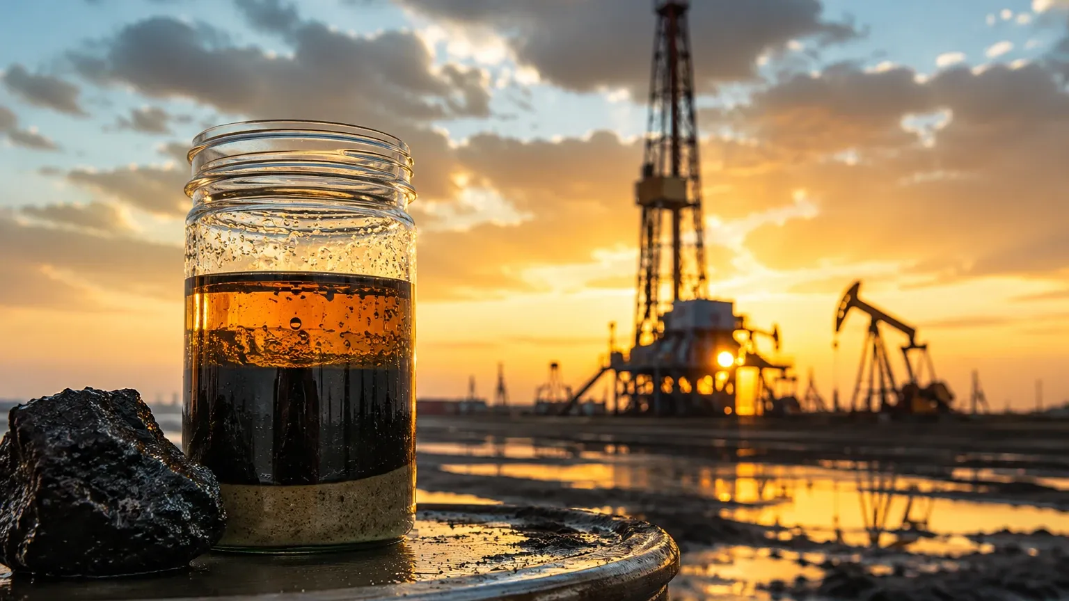
Oil and gas separation is rarely a clean process. Several factors can interfere with level measurement accuracy:
* Emulsions and Rag Layers: In three-phase separators, a "rag layer" (a mixture of oil, water, and solids) often forms at the interface. This layer can be several centimeters thick and lacks a sharp dielectric break, which can confuse radar signals. Low-frequency radar or specialized GWR algorithms are often required to track the middle of the rag layer.
* Paraffin and Wax Deposition: In colder climates or with specific crude types, wax can build up on GWR probes or magnetic floats. This increases the diameter of the probe or the weight of the float, leading to errors. Maintenance schedules must include periodic cleaning, or heated bypass chambers may be used.
* Foaming: High-pressure drops at the inlet can cause crude oil to foam. Foam absorbs ultrasonic signals and can scatter radar pulses. If foaming is persistent, mechanical foam breakers are needed, or the use of GWR (which can often see through light foam) is preferred over non-contact methods.
Frequently Asked Questions (FAQ)
Q: Can a single instrument measure both oil and water levels?
A: Yes, Guided Wave Radar (GWR) is specifically designed for this. It detects the first reflection from the oil surface and a second, stronger reflection from the water interface.
Q: How does pressure affect level measurement?
A: Pressure primarily affects the density of the vapor space. For hydrostatic sensors, it requires a DP setup to cancel out the head pressure. For radar, extremely high pressure may require gas phase compensation to maintain sub-millimeter accuracy.
Q: What is the benefit of a bypass chamber (external cage)?
A: A bypass chamber allows for maintenance and calibration without shutting down the separator. By using isolation valves, the instrument can be removed while the vessel remains pressurized.
Q: Is ultrasonic technology suitable for separator vessels?
A: Generally, no. The fluctuating gas composition and high pressures in oil and gas separation make the speed of sound unpredictable, leading to significant measurement errors.
Conclusion
Successful oil and gas separation is the foundation of efficient production. By understanding the principles of GWR, hydrostatic pressure, and radar, engineers can implement control strategies that prevent equipment damage and optimize the purity of the output streams. While challenges like rag layers and wax buildup persist, proper technology selection and adherence to installation best practices mitigate these risks. For those in the procurement or engineering phase of a project, visiting the Main Page of an established instrument manufacturer like Welk can provide the technical data sheets and application support necessary to ensure a reliable installation.