
Optical Analysis
Optical Analysis
In the field of industrial process control, optical analysis serves as a sophisticated method for determining the presence, distance, and characteristics of materials within a vessel. While traditional mechanical or pressure-based systems remain common, optical technologies leverage the properties of light—reflection, refraction, and time-of-flight—to provide non-contact or minimally invasive measurements. This guide explores the engineering principles behind optical level measurement, its practical applications, and the criteria necessary for successful deployment in demanding industrial environments.
The Role of Optical Analysis in Industrial Level Measurement
Optical analysis in level measurement typically refers to the use of light-emitting diodes (LEDs) or laser sources to detect the interface between two media (such as air and liquid) or to measure the distance to a surface. Unlike ultrasonic sensors that rely on sound waves or radar sensors that use electromagnetic radio waves, optical systems utilize the visible or infrared spectrum.
This technology is particularly valued in applications where the media may be highly corrosive, non-conductive, or situated in environments where extremely narrow beams are required to avoid internal tank obstructions. By analyzing how light interacts with a substance, engineers can achieve high-precision point level detection or continuous distance monitoring. For those evaluating these technologies against other instrumentation, the Main Page provides a comprehensive starting point to review product options and application support.
Measurement Principles of Optical Level Technologies
To effectively implement optical analysis, it is essential to understand the two primary physical principles employed: refraction/reflection for point level detection and time-of-flight for continuous measurement.
1. Refraction and Internal Reflection (Point Level)
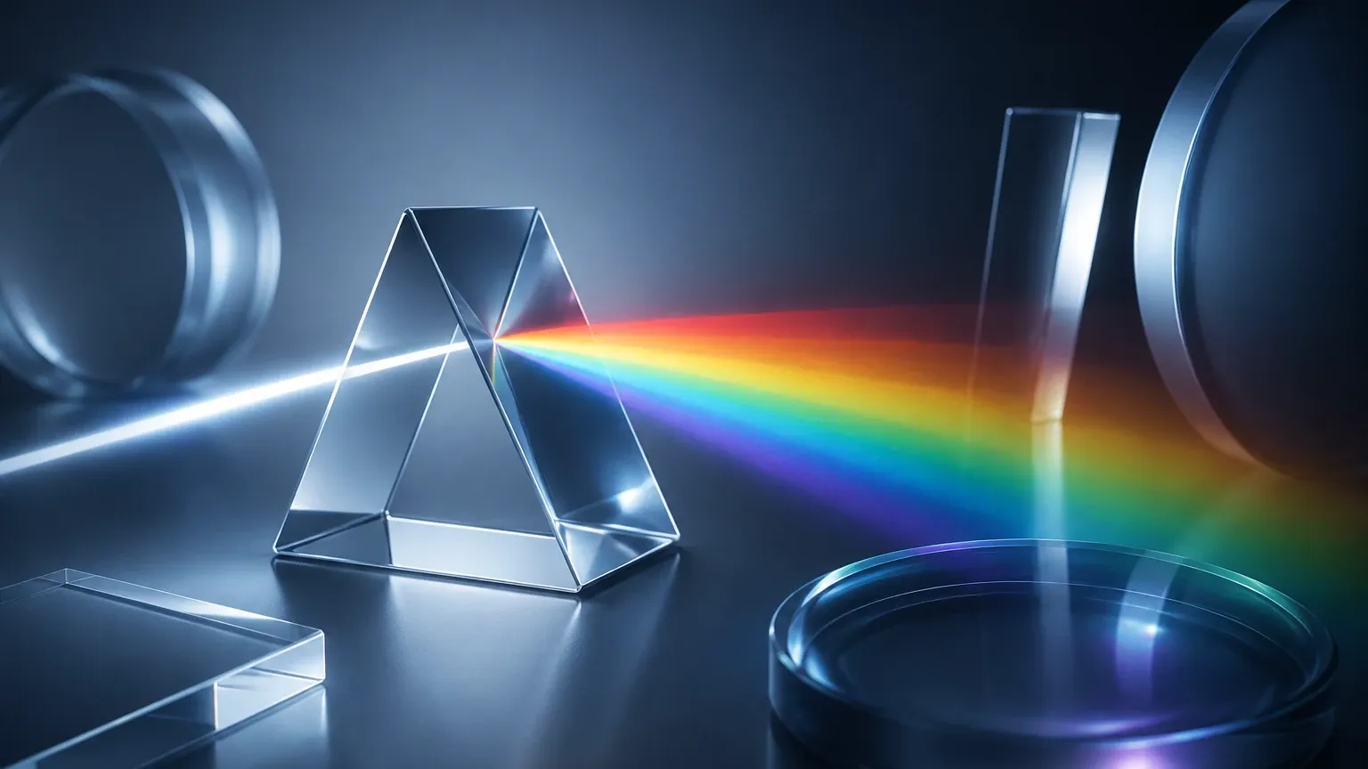
Most optical point level sensors consist of an infrared LED and a light receiver (phototransistor) housed within a plastic or glass tip, often shaped as a prism.
* In Air: When the sensor tip is surrounded by gas or air, the light emitted by the LED is internally reflected within the prism back to the receiver. The sensor interprets this high-intensity return signal as a "dry" state.
* In Liquid: When the prism is submerged, the refractive index of the liquid (which is closer to the refractive index of the prism material than air is) causes the light to escape into the fluid. The amount of light reflected back to the receiver drops significantly. This change is analyzed by the electronics to trigger a "wet" state.
2. Laser Time-of-Flight (Continuous Level)
Continuous optical analysis often utilizes laser transmitters. These devices emit a pulse of light toward the material surface. The system measures the time it takes for the pulse to travel to the surface and reflect back to the sensor.
Because the speed of light is a known constant (approximately 300,000 km/s), the distance (D) can be calculated using the formula:
D = (c × t) / 2
Where:
* c is the speed of light.
* t is the measured transit time.
Laser-based optical analysis offers an extremely narrow beam angle (often less than 0.3°), allowing it to measure through narrow openings or near-vessel walls without the interference issues common to ultrasonic or radar technologies.
Practical Selection Criteria for Optical Level Systems
Selecting the correct instrument requires a detailed optical analysis of the application environment. Factors such as fluid transparency, reflectivity, and ambient light must be accounted for. The following table provides a baseline for comparing optical technologies with standard industrial requirements.
| Feature | Optical Point Sensor | Laser Level Transmitter |
| :— | :— | :— |
| Measurement Type | Point (On/Off) | Continuous (0-100% level) |
| Accuracy | High (±1 mm) | High (±2 mm to ±10 mm) |
| Media Compatibility | Clean, non-coating liquids | Solids, opaque liquids, molten metals |
| Beam Angle | N/A | Extremely Narrow (<1°) |
| Pressure Range | Up to 50 bar (typical) | Up to 100 bar (specialized) |
| Temperature Range | -40°C to +125°C | -40°C to +2000°C (with cooling) |
| Maintenance | Low (if no coating) | Low (requires clean lens) |
Comparison with Radar and Ultrasonic Technologies
Engineers often choose optical analysis when other non-contact methods fail due to specific physical constraints:
* Vs. Ultrasonic: Ultrasonic sensors are affected by changes in air temperature, pressure, and vapor composition because these factors change the speed of sound. Optical signals are largely unaffected by these atmospheric variations, making them more stable in vacuum or high-pressure gas environments.
* Vs. Radar: Radar measurement depends on the dielectric constant (Dk) of the material. Materials with a very low Dk (like certain hydrocarbons) are difficult for radar to detect. Optical analysis depends on reflectivity or refraction, meaning it can often detect low-Dk materials effectively as long as they are not perfectly transparent to the specific wavelength used.
Installation Considerations and Best Practices
Successful deployment of optical instruments depends heavily on correct installation to ensure the integrity of the optical path.
1. Orientation and Alignment: For continuous laser measurement, the sensor must be mounted perpendicular to the target surface. For point level sensors, horizontal mounting is often preferred to allow liquid to drain off the prism tip easily, preventing false "wet" readings due to droplets.
2. Ambient Light Interference: While modern sensors use modulated light to filter out background noise, extremely bright environments or direct sunlight can occasionally saturate the receiver. Using sunshades or recessed mounting can mitigate this risk.
3. Lens Maintenance: Optical analysis requires a clear line of sight. In applications with heavy dust, mist, or splashing, the use of a "purge bridge" or air-wipe system is recommended. This involves a low-pressure air stream that keeps the lens surface free of contaminants.
4. Vessel Obstructions: Because of the narrow beam, optical sensors excel in tanks with agitators, heating coils, or ladders. However, the path must be completely clear of fixed obstructions to prevent false distance readings.
Limitations and Application Risks
Despite its precision, optical analysis is not a universal solution. Engineers must be aware of the following limitations:
* Coating and Buildup: If the media is highly viscous or prone to crystallization, a film may form over the sensor tip. For point level sensors, this film can trap light and cause a permanent "wet" signal.
* Foam: Heavy, dense foam can be problematic. Depending on the wavelength, the light may be absorbed by the foam or reflected off the top of the foam layer rather than the liquid surface. If the goal is to measure the liquid level beneath the foam, optical analysis may not be the optimal choice.
* Transparency: For point level sensors, the liquid must have a different refractive index than the prism. For continuous laser measurement, the material must be sufficiently opaque or reflective to return the signal. Extremely clear liquids may require the laser to be aimed at a float or a reflective plate.
Industrial Applications for Optical Analysis
* Pharmaceutical and Biotech: Used for high-precision detection of fluids in small-diameter tubing or micro-reactors where traditional probes cannot fit.
* Food and Beverage: Detecting the presence of clear liquids in bottling lines or monitoring the level of dry ingredients in narrow silos.
* Metal Processing: Laser-based optical analysis is one of the few technologies capable of measuring the level of molten metals by utilizing high-temperature specialized optics and cooling jackets.
* Leak Detection: Optical point sensors are frequently installed in the interstitial spaces of double-walled tanks to detect leaks immediately.
Frequently Asked Questions (FAQs)
Q: Can optical sensors detect clear water?
A: Yes. Point level sensors use refraction, which works perfectly with clear water because the refractive index of water (approx. 1.33) is significantly different from air (1.0). Continuous laser sensors can also detect water, though they may require a specific angle or a slightly turbulent surface to ensure a return signal.
Q: How does steam or heavy vapor affect optical analysis?
A: Light is scattered by water droplets. While light can penetrate thin vapors better than ultrasonic waves can, extremely dense steam will attenuate the optical signal, potentially reducing the effective range of a laser transmitter.
Q: Is the laser used in these sensors dangerous to operators?
A: Most industrial laser level meters use Class 1 or Class 2 lasers. Class 1 is eye-safe under all conditions. Class 2 is safe for accidental viewing because the blink reflex will protect the eye. However, standard safety protocols should always be followed during installation and maintenance.
Q: What is the typical lifespan of the LED or Laser source?
A: High-quality industrial optical sensors are rated for 50,000 to 100,000 hours of continuous operation. In many applications, this translates to over 10 years of service life.
For engineers requiring detailed technical specifications or customized OEM/ODM solutions for level measurement, visiting the Main Page allows for a deeper dive into the specific hardware configurations that support these optical principles.


