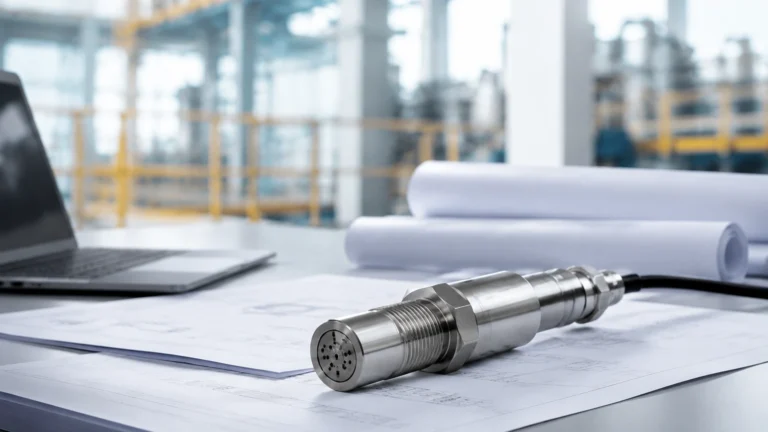
Oxy Lc 485
Oxy Lc 485
In the landscape of industrial process control and environmental monitoring, the integration of digital communication protocols with high-precision sensors has become a standard requirement. The oxy lc 485 represents a specialized category of oxygen sensors equipped with an RS485 interface, typically utilizing the Modbus RTU protocol. This configuration is essential for modern automation systems where long-distance signal transmission, noise immunity, and multi-parameter data acquisition are critical. While level measurement remains a primary focus for many industrial facilities, the simultaneous monitoring of dissolved or gaseous oxygen levels provides a more holistic view of process health, particularly in water treatment, chemical synthesis, and aquaculture.
Measurement Principles of Oxygen Sensors
Before selecting or implementing an oxy lc 485 system, it is vital to understand the underlying physics of oxygen measurement. In industrial contexts, oxygen is generally measured in two forms: Dissolved Oxygen (DO) in liquids or gaseous oxygen in headspaces. There are two primary technologies used in these sensors.
1. Optical (Fluorescence Quenching) Principle
Optical oxygen sensors are increasingly preferred in B2B applications due to their low maintenance and high stability. These sensors utilize a sensing cap coated with a luminophore. A blue light source excites the luminophore, which then emits red light. When oxygen molecules come into contact with the sensing element, they "quench" the fluorescence. The phase shift or the duration of the fluorescence is inversely proportional to the concentration of oxygen.
This method is non-consumptive, meaning the sensor does not "use up" oxygen during measurement, making it ideal for low-flow environments. Furthermore, optical sensors are not affected by common interferents like hydrogen sulfide ($H_2S$), which can poison traditional electrochemical cells.
2. Electrochemical (Polarographic or Galvanic) Principle
Electrochemical sensors rely on a chemical reaction. A cathode and an anode are submerged in an electrolyte solution, separated from the process medium by a gas-permeable membrane. Oxygen diffuses through the membrane and is reduced at the cathode, creating an electrical current. The magnitude of this current is directly proportional to the partial pressure of oxygen. While cost-effective, these sensors require regular membrane replacement and electrolyte replenishment, and they require a minimum flow rate to ensure a fresh supply of oxygen reaches the membrane.
The Role of RS485 (Modbus RTU) in Oxygen Monitoring
The "485" in oxy lc 485 refers to the TIA/EIA-485 physical layer. This differential signaling standard is robust against electromagnetic interference (EMI), which is prevalent in industrial environments near pumps, motors, and high-voltage lines.
By using RS485, the oxy lc 485 sensor can communicate over distances up to 1,200 meters without the signal degradation associated with 4-20mA analog loops. Furthermore, the Modbus RTU protocol allows for "daisy-chaining" multiple sensors on a single twisted-pair cable. This significantly reduces wiring costs and simplifies the integration of oxygen data with other process variables, such as those found on the Main Page of a comprehensive process control platform.
Key Evaluation Criteria for Selection
When specifying an oxy lc 485 sensor for a project, engineers must evaluate several technical parameters to ensure long-term reliability and accuracy.
| Feature | Specification Detail | Importance |
| :— | :— | :— |
| Measurement Range | 0–20 mg/L or 0–200% Saturation | Defines the suitability for aerobic vs. anaerobic processes. |
| Pressure Rating | Up to 2 bar (200 kPa) or higher | Critical for pressurized pipe installations or deep tank submersion. |
| Temperature Compensation | Automatic (ATC) via internal NTC/PT1000 | Oxygen solubility is highly temperature-dependent. |
| Material Compatibility | 316L Stainless Steel, PVC, or Titanium | Essential for corrosive chemical or seawater applications. |
| Response Time ($T_{90}$) | < 60 seconds | Determines how quickly the system reacts to process upsets. |
| Communication | RS485 Modbus RTU | Ensures compatibility with PLCs, SCADA, and IoT gateways. |
Practical Applications in Industry
Wastewater Treatment
In activated sludge processes, maintaining optimal dissolved oxygen levels in aeration tanks is the most energy-intensive part of the plant. An oxy lc 485 sensor provides the real-time data necessary to control blowers. If DO levels are too low, the bacteria die; if they are too high, energy is wasted. The digital output allows for precise PID control loops.
Chemical and Pharmaceutical Manufacturing
Many chemical reactions are sensitive to oxygen. In these environments, oxygen sensors are often used in conjunction with hydrostatic level transmitters to monitor both the volume of the reactant and its chemical state. The RS485 interface allows these diverse sensors to share a single communication bus back to the control room.
Aquaculture and Hydroponics
For large-scale fish farming, oxygen depletion can lead to catastrophic stock loss within minutes. The oxy lc 485 is used in multi-point monitoring systems where dozens of tanks are monitored simultaneously. The digital nature of the sensor allows for easy calibration logging and sensor health diagnostics directly from the central management software.
Installation Considerations and Best Practices
Proper installation is paramount to the performance of any oxy lc 485 device. Engineers should adhere to the following guidelines:
1. Mounting Angle: Sensors should typically be mounted at an angle (usually 15° to 45° from the vertical) to prevent air bubbles from collecting on the sensing face, which would cause falsely high readings.
2. Flow Requirements: For electrochemical sensors, ensure a minimum flow velocity (often 0.3 m/s). Optical sensors are less sensitive to flow but still require representative sampling of the bulk liquid.
3. Cable Shielding: Use shielded twisted-pair (STP) cabling for the RS485 lines. The shield should be grounded at a single point (usually the PLC end) to prevent ground loops.
4. Termination Resistors: In long RS485 networks, a 120-ohm termination resistor must be placed at the beginning and the end of the bus to prevent signal reflections.
5. Submergence Depth: Ensure the sensor’s IP rating (typically IP68) and pressure rating match the maximum depth of the tank. For deep tanks, specialized mounting hardware or stilling wells may be required.
Limitations and Common Risks
While the oxy lc 485 is a robust solution, it is not without limitations.
* Biofouling: In wastewater or biological processes, biofilm can grow on the sensor membrane or cap. This creates a barrier that slows response time and reduces accuracy. Regular cleaning or the use of sensors with integrated wipers or air-blast cleaning systems is recommended.
* Salinity Interference: Dissolved oxygen solubility decreases as salinity increases. If the application involves brackish water or brine, the sensor or the controlling PLC must account for salinity compensation (often a manual entry of the salinity value into the Modbus register).
* Signal Isolation: In environments with heavy electrical noise, non-isolated RS485 ports can lead to communication failures or even hardware damage. Choosing a sensor with internal galvanic isolation is a prudent engineering choice.
Maintenance and Calibration Protocols
Digital sensors like the oxy lc 485 often store calibration data internally. This allows for "plug-and-play" replacement where a sensor can be calibrated in a laboratory and then deployed to the field without requiring on-site adjustments.
* Zero-Point Calibration: Performed in an oxygen-free environment (e.g., water with dissolved sodium sulfite or 100% nitrogen gas). This is critical for accurate measurements at low oxygen concentrations.
* Slope Calibration (Span): Usually performed in air-saturated water or water-saturated air. Since the partial pressure of oxygen in the atmosphere is well-known, this is a reliable reference point.
* Cap/Membrane Replacement: Optical caps typically last 1–2 years depending on the environment. Electrochemical membranes may need service every 3–6 months.
Frequently Asked Questions (FAQ)
Q: Can the oxy lc 485 be used in hazardous areas?
A: Many versions are available with ATEX or IECEx certifications for use in explosive atmospheres. Always verify the specific Ex rating (e.g., Ex ia IIC T4 Ga) before installation in such zones.
Q: How many oxy lc 485 sensors can I connect to a single PLC port?
A: Theoretically, a Modbus RTU network can support up to 247 nodes. However, due to electrical loading and polling speed requirements, most industrial segments limit this to 32 sensors per segment before using a repeater.
Q: Does the sensor require a specific controller?
A: No. Because it uses the standard Modbus RTU protocol over RS485, it can communicate with any PLC, HMI, or PC-based data acquisition system that supports these standards.
Conclusion for Project Planning
Selecting the right oxy lc 485 involves more than just checking a specification sheet. It requires an understanding of the process medium, the physical constraints of the installation site, and the integration requirements of the existing control architecture. By prioritizing digital communication, facilities can achieve higher data integrity and lower long-term maintenance costs. For those integrating oxygen monitoring into broader liquid management systems, exploring the variety of measurement technologies available on the Main Page can help in designing a cohesive and efficient instrumentation strategy. Before proceeding, project managers should confirm the chemical compatibility of the sensor body with the process fluid and ensure that the chosen communication parameters (baud rate, parity, and stop bits) align with the site’s networking standards.