Plating Tank
Plating Tank
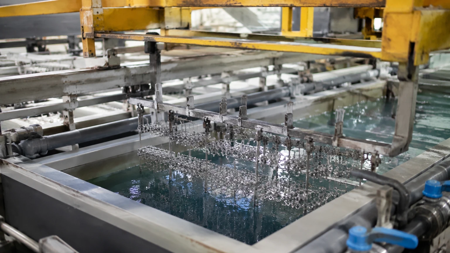
In the surface finishing and electroplating industry, the management of a plating tank is a critical factor in ensuring product quality, operational safety, and chemical efficiency. These tanks contain complex chemical solutions—often highly corrosive acids or alkaline baths—that must be maintained at precise levels to facilitate the electrochemical process. Level measurement in a plating tank is challenging due to the presence of corrosive fumes, steam, surface foam, and the physical constraints of the tank itself.
Effective level monitoring prevents dry-running of heaters, avoids tank overflows that could lead to hazardous spills, and ensures that the surface area of the submerged workpieces remains consistent. This article provides an engineering perspective on selecting and installing level measurement technologies specifically for plating environments.
Measurement Principles for Plating Applications
Before selecting a specific instrument, it is essential to understand the physical principles governing the most common measurement technologies used in plating facilities.
Radar Level Measurement (Non-Contact)
Radar level transmitters operate on the Time-of-Flight (ToF) principle. The device emits high-frequency microwave pulses (typically in the 26 GHz or 80 GHz range) toward the liquid surface. These pulses are reflected back to the sensor. The distance is calculated based on the time taken for the pulse to travel to the surface and back.
In a plating tank, high-frequency 80 GHz radar is often preferred because it offers a narrow beam angle. This allows the signal to avoid internal obstructions such as heating coils, anodes, and cathode bars. Radar is generally unaffected by temperature fluctuations, vacuum, or high pressure, making it a robust choice for volatile chemical baths.
Ultrasonic Level Measurement (Non-Contact)
Ultrasonic sensors also use the Time-of-Flight principle but employ sound waves instead of microwaves. The sensor emits an ultrasonic pulse that reflects off the liquid surface. The time elapsed is proportional to the distance.
While cost-effective, ultrasonic measurement is sensitive to the medium through which the sound travels. In plating tanks, heavy steam, dense chemical vapors, or significant temperature gradients can alter the speed of sound, leading to measurement errors unless the sensor features integrated temperature compensation. Furthermore, certain chemicals can degrade the transducer face if it is not properly shielded with chemically resistant materials like PVDF (Polyvinylidene fluoride).
Hydrostatic Pressure Measurement (Contact)
Hydrostatic level transmitters measure the pressure exerted by the liquid column above the sensor. The principle is based on the formula: $P = \rho \cdot g \cdot h$, where $P$ is pressure, $\rho$ (rho) is the density of the liquid, $g$ is gravity, and $h$ is the height of the liquid.
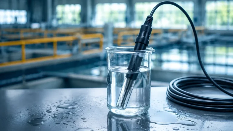
For a plating tank, submersible pressure transducers or flange-mounted sensors are used. Because the sensor is in direct contact with the electrolyte, the diaphragm and housing must be constructed from highly corrosion-resistant materials such as ceramic, Tantalum, or Hastelloy-C, often paired with PTFE-coated cables.
Magnetic Level Gauges
Magnetic level gauges utilize a float containing a magnet that moves within a bypass chamber mounted to the side of the tank. As the float rises and falls with the liquid level, it flips magnetic flags or activates a reed chain transmitter on the outside of the chamber. This provides both a visual indication and an electronic signal. This method is highly reliable for pressurized tanks but requires a bypass installation, which may not be feasible for all plating tank configurations.
Technology Selection Criteria
Choosing the right instrument for a plating tank requires a detailed analysis of the chemical and physical environment. For more information on specific hardware options, engineers can Review product options and application support on the Main Page.
Chemical Compatibility
The primary concern in any plating application is corrosion. The electrolyte solutions—whether they are chromic acid, sulfuric acid, or cyanide-based alkaline baths—will rapidly degrade standard stainless steel.
- Non-contact sensors: Ensure the housing and the antenna/transducer face are made of PVDF, PTFE, or PP (Polypropylene).
- Contact sensors: Diaphragms should be ceramic or specialized alloys. Submersible cables must be FEP or PTFE jacketed to prevent acid wicking.
Presence of Steam and Vapors
Many plating processes, such as hot nickel or chrome plating, operate at elevated temperatures (e.g., 50°C to 80°C). This results in significant steam and chemical vapors.
- Radar is largely immune to these vapors.
- Ultrasonic may struggle if the vapor density changes rapidly or if condensation forms on the transducer face.
Surface Conditions
Agitation (air or mechanical) and the presence of surfactants often create foam on the surface of a plating tank.
- Radar can penetrate light foam, but heavy, dense foam may absorb the microwave signal.
- Ultrasonic signals are often scattered or absorbed by foam, leading to "signal lost" errors.
- Hydrostatic and Magnetic sensors are unaffected by surface foam as they measure based on mass or buoyancy.
Comparison Table: Level Measurement Technologies
| Feature | Radar (80 GHz) | Ultrasonic | Hydrostatic | Magnetic Gauge |
| :— | :— | :— | :— | :— |
| Contact Type | Non-contact | Non-contact | Contact | Contact (via bypass) |
| Corrosion Resistance | Excellent (with PTFE/PVDF) | Good (with PVDF) | Variable (depends on alloy) | Excellent (if plastic-lined) |
| Steam/Vapor Handling| Excellent | Moderate to Poor | Excellent | Excellent |
| Foam Sensitivity | Low | High | None | None |
| Accuracy | ±1 mm to ±2 mm | ±0.25% of range | ±0.1% to ±0.5% | ±5 mm to ±10 mm |
| Installation Complexity| Low (Top mount) | Low (Top mount) | Moderate (Bottom/Subm) | High (Bypass piping) |
| Typical Cost | High | Low to Moderate | Moderate | Moderate to High |
Installation Considerations for Plating Tanks
Proper installation is as critical as technology selection. In the confined space of a plating tank, several factors must be addressed:
1. Beam Angle and Obstructions: For radar and ultrasonic sensors, the "beam" expands as it travels. Ensure the sensor is mounted away from the tank wall and clear of anodes, cathode bars, and heating elements. A 100 mm (approx. 4 inch) clearance from the wall is a standard minimum for high-frequency radar.
2. Dead Zones (Blocking Distance): Every non-contact sensor has a "dead zone" directly beneath the transducer where measurement is impossible. Ensure the sensor is mounted high enough so that the maximum liquid level does not enter this zone. Typically, this is between 50 mm and 250 mm depending on the model.
3. Stilling Wells: If the tank has extreme agitation or heavy foam, installing the sensor inside a stilling well (a vertical pipe) can provide a calm liquid surface for more accurate measurement. The pipe must have vent holes to equalize pressure and liquid level.
4. Mounting Materials: Avoid using metallic mounting brackets that could be corroded by rising fumes. Use plastic flanges or brackets specifically designed for chemical environments.
5. Cable Protection: For submersible hydrostatic sensors, ensure the cable is secured so it does not drift into the path of moving workpieces or agitation systems.
Limitations and Operational Challenges
While modern instrumentation is highly advanced, certain limitations remain in the plating environment:
* Crystallization: Some plating solutions, like zinc or copper baths, can form crystals as they cool or evaporate. If these crystals build up on a radar antenna or an ultrasonic transducer, the signal will degrade. Regular inspection and cleaning with deionized water are necessary.
* Density Changes: Hydrostatic sensors are calibrated based on the specific gravity of the liquid. If the concentration of the plating bath changes significantly, the level reading will shift. Engineers must recalibrate the sensor if the bath chemistry is modified.
| Dielectric Constant: Radar relies on the dielectric constant (εr) of the liquid. Most aqueous plating solutions have a high dielectric constant (εr > 20), making them easy to detect. However, some organic solvent-based cleaners used in pre-treatment may have low dielectric constants, requiring more sensitive radar settings.
Frequently Asked Questions (FAQ)
Q: Can I use a standard stainless steel sensor in a chrome plating tank?
A: No. Hexavalent or trivalent chromium will rapidly corrode 316L stainless steel. You must use sensors with wetted parts made of PTFE, PVDF, or specialized ceramic diaphragms.
Q: How do I handle level measurement in a tank with a heavy layer of foam?
A: Hydrostatic pressure sensors are usually the best choice for foamy tanks because they measure the liquid head pressure and are not confused by the air-filled foam. If non-contact is required, a radar sensor with a stilling well is the next best option.
Q: What is the benefit of 80 GHz radar over 26 GHz radar for plating?
A: The 80 GHz radar has a much narrower beam (often as small as 3 degrees). Plating tanks are often crowded with racks and electrodes; a narrow beam can "see" between these objects to the liquid surface without interference.
Q: Is periodic calibration required for plating tank level sensors?
A: Yes. For hydrostatic sensors, calibration should be checked whenever the bath density changes. For radar and ultrasonic sensors, an annual check is recommended to ensure no chemical buildup has occurred on the sensor face.
Conclusion
Maintaining the correct liquid level in a plating tank is essential for process stability and safety. While ultrasonic sensors offer a cost-effective solution for simple applications, the demanding conditions of heat, vapor, and corrosion often make 80 GHz radar or specialized hydrostatic transmitters the more reliable choice for long-term industrial use. By matching the sensor material to the bath chemistry and accounting for internal tank obstructions during installation, facilities can achieve precise, maintenance-free level control. For further technical guidance and to explore specific measurement solutions, visit the Main Page.