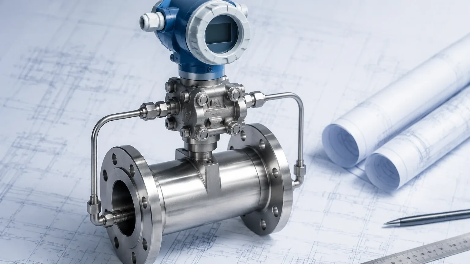
Pressure Differential Flow Meter
Pressure Differential Flow Meter
In the landscape of industrial process control, the pressure differential flow meter remains one of the most versatile and widely adopted technologies for measuring the flow rate of liquids, gases, and steam. Based on centuries-old fluid mechanics principles, these instruments provide a robust solution for diverse sectors, including water treatment, chemical processing, and oil and gas production. Understanding the technical nuances of these meters is essential for engineers tasked with optimizing system efficiency and ensuring measurement accuracy.
The Fundamental Principle of Differential Pressure Measurement
The operation of a pressure differential flow meter is rooted in Bernoulli’s principle, which describes the relationship between the velocity of a fluid and its pressure. When a fluid moving through a closed pipe encounters a physical restriction, its velocity increases according to the principle of continuity. Simultaneously, as the kinetic energy increases, the static pressure of the fluid decreases.
By measuring the difference in pressure between a point upstream of the restriction and a point at or immediately downstream of the restriction, the flow rate can be calculated. This relationship is mathematically expressed where the flow rate (Q) is proportional to the square root of the differential pressure (ΔP).
A complete measurement system typically consists of two main components:
1. The Primary Element: The physical device installed in the pipeline to create the pressure drop (e.g., an orifice plate or Venturi tube).
2. The Secondary Element: The differential pressure transmitter that senses the pressure change and converts it into an electrical signal, such as a 4-20mA or digital output, which represents the flow rate.
Types of Primary Elements
Selecting the correct primary element is the most critical step in designing a pressure differential flow meter system. Each type offers distinct advantages regarding accuracy, pressure recovery, and suitability for specific fluid types.
Orifice Plates
The orifice plate is the most common primary element due to its simplicity and low initial cost. It consists of a thin metal plate with a precisely machined hole (bore) in the center. While highly effective for clean liquids and gases, the sharp edge of the orifice creates significant turbulence, leading to a high permanent pressure loss (PPL). Over time, erosion of the orifice edge can degrade measurement accuracy.
Venturi Tubes
Venturi tubes feature a tapered inlet and a diverging outlet. This streamlined design allows the fluid to regain much of its static pressure after passing through the throat. Venturi tubes are ideal for applications where minimizing energy loss is critical or where the fluid contains suspended solids that might clog an orifice plate. Although they are more expensive and require more space for installation, their longevity and low maintenance requirements often justify the investment.
Flow Nozzles
Flow nozzles act as a middle ground between orifice plates and Venturi tubes. They are particularly effective for high-velocity flows and erosive fluids, such as high-pressure steam. The contoured inlet of the nozzle is less susceptible to wear than the sharp edge of an orifice plate, ensuring better long-term stability in harsh environments.
Pitot Tubes and Averaging Pitot Tubes
Unlike other elements that restrict the entire flow stream, Pitot tubes measure the difference between the impact pressure (stagnation pressure) and the static pressure at a specific point in the flow. Averaging Pitot tubes use multiple sensing ports across the pipe diameter to provide a more representative measurement of the flow profile. These are favored for large diameter pipes where installing a full-bore restriction would be cost-prohibitive.
Technical Selection Criteria
When evaluating a pressure differential flow meter for a specific project, engineers must balance several technical factors. The following table provides a comparative overview of the most common primary elements.
| Feature | Orifice Plate | Venturi Tube | Flow Nozzle | Averaging Pitot Tube |
| :— | :— | :— | :— | :— |
| Accuracy | ±0.6% to ±2% | ±0.5% to ±1.5% | ±0.8% to ±2% | ±1% to ±3% |
| Permanent Pressure Loss | High (60-80% of ΔP) | Low (10-20% of ΔP) | Moderate (40-60% of ΔP) | Very Low |
| Relative Cost | Low | High | Moderate | Low to Moderate |
| Suitability for Slurries | Poor | Excellent | Fair | Poor |
| Required Straight Run | High | Low | Moderate | Moderate |
Installation Considerations and Best Practices
The accuracy of a pressure differential flow meter is heavily dependent on the quality of the installation. Even the most precise transmitter cannot compensate for poor hydraulic conditions upstream of the primary element.
Straight Pipe Requirements
To ensure a fully developed and predictable flow profile, the meter must be preceded and followed by straight sections of pipe. Obstructions such as elbows, valves, and pumps create swirls and velocity profile distortions. Typically, a minimum of 10 to 20 pipe diameters (D) upstream and 5D downstream is recommended. If space is limited, flow conditioners or straightening vanes may be required to maintain accuracy.
Impulse Line Routing
Impulse lines connect the primary element to the differential pressure transmitter. These lines must be installed with a slope (typically 1:12) to allow trapped air to escape back into the pipe (in liquid applications) or to allow condensate to drain (in gas applications). For high-temperature applications, such as steam flow, the impulse lines also serve to cool the process fluid before it reaches the sensitive transmitter diaphragms.
Orientation
The orientation of the pressure taps depends on the fluid phase:
* Liquids: Taps should be located on the side of the pipe to prevent sediment from entering the lines and to ensure they remain filled with liquid.
* Gases: Taps should be located at the top of the pipe to prevent moisture or condensate from entering the transmitter.
* Steam: Taps are usually located on the side, with condensate pots used to maintain a constant liquid head on the transmitter.
Limitations and Challenges
While the pressure differential flow meter is a workhorse of industry, it is not without limitations. One of the primary challenges is the turndown ratio. Because the flow rate is proportional to the square root of the differential pressure, a 10:1 reduction in flow results in a 100:1 reduction in the ΔP signal. Most standard DP systems are limited to a 3:1 or 4:1 turndown ratio while maintaining acceptable accuracy. Modern multi-variable transmitters can extend this range by compensating for changes in fluid density, temperature, and pressure.
Another consideration is Permanent Pressure Loss (PPL). In large-scale pumping systems, the energy required to overcome the pressure drop created by an orifice plate can result in significant annual electricity costs. In such cases, selecting a low-loss device like a Venturi tube or an ultrasonic flow meter may be more cost-effective over the equipment's lifecycle.
Synergy with Level Measurement
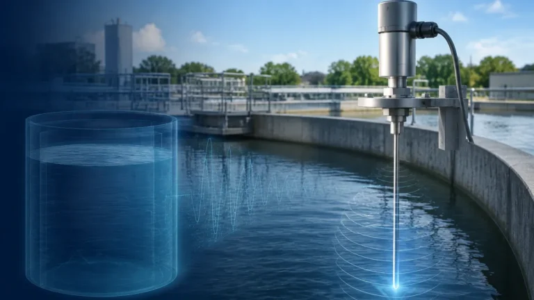
It is worth noting that the core technology used in the secondary element of a flow system—the differential pressure transmitter—is identical to the technology used for hydrostatic level measurement. In pressurized vessels, a DP transmitter measures the pressure difference between the liquid bottom and the vapor space to determine the liquid level. For professionals managing industrial facilities, sourcing these instruments from a unified Main Page allows for better parts standardization and simplified maintenance routines. Manufacturers like Welk provide integrated solutions that cover both flow and level requirements, ensuring compatibility across the control loop.
Frequently Asked Questions (FAQ)
Q: How does fluid viscosity affect a pressure differential flow meter?
A: DP meters are sensitive to the Reynolds number, which is a function of viscosity. At low Reynolds numbers (highly viscous fluids), the flow profile changes, and the discharge coefficient of the primary element may no longer be constant. Special orifice designs, such as quadrant edge or conical entrance orifices, are used for high-viscosity applications.
Q: Can these meters be used for bidirectional flow?
A: Standard orifice plates and Venturi tubes are designed for unidirectional flow. However, symmetrical primary elements or specialized bi-directional DP transmitters can be used if the application requires measuring flow in both directions.
Q: What maintenance is required for a DP flow meter?
A: Maintenance typically involves periodic calibration of the DP transmitter and inspection of the impulse lines for leaks or blockages. In erosive or corrosive services, the primary element (especially orifice plates) should be inspected for wear, as any rounding of the sharp edge will lead to under-measurement of the flow.
Q: Why is square root extraction necessary?
A: Since the differential pressure produced is proportional to the square of the flow velocity, the transmitter or the control system must perform a square root calculation to convert the pressure signal into a linear flow signal. Without this, the reading would be exponentially skewed.
Conclusion
The pressure differential flow meter remains a cornerstone of industrial instrumentation due to its predictable performance, lack of moving parts, and deep theoretical foundation. By carefully selecting the primary element and adhering to strict installation standards regarding straight pipe runs and impulse line routing, engineers can achieve reliable and accurate flow data for even the most demanding applications. For those looking to integrate these systems into broader process automation frameworks, reviewing the latest advancements in transmitter technology and level measurement integration on the Main Page is a recommended next step in project planning.