Pressure Differential Transmitter
Pressure Differential Transmitter
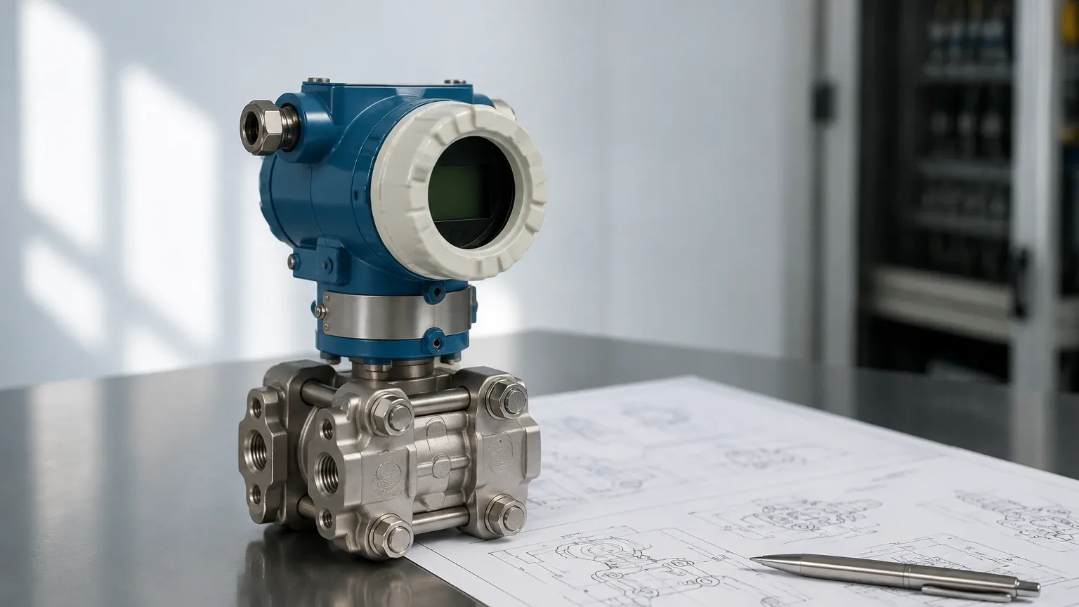
In the landscape of industrial process control, the pressure differential transmitter stands as one of the most versatile and widely utilized instruments for level, flow, and pressure measurement. Often abbreviated as a DP transmitter, this device measures the difference between two pressure points and converts that physical difference into an electrical signal, typically a 4-20mA analog output or a digital protocol such as HART, Foundation Fieldbus, or Profibus.
For engineers and plant operators, understanding the nuances of these instruments is critical for ensuring process safety, efficiency, and accuracy. This guide provides a technical overview of the measurement principles, selection criteria, installation requirements, and common challenges associated with the pressure differential transmitter in industrial environments.
Fundamental Principles of Differential Pressure Level Measurement
The operation of a pressure differential transmitter is rooted in the principles of fluid mechanics, specifically hydrostatic pressure. When used for level measurement, the transmitter calculates the height of a liquid column by measuring the pressure exerted by that column at the base of a vessel.
The Hydrostatic Equation
The basic formula governing this measurement is:
P = ρ · g · h
Where:
* P is the hydrostatic pressure (measured in Pascals or bar).
* ρ (rho) is the density of the liquid (kg/m³).
* g is the acceleration due to gravity (approximately 9.81 m/s²).
* h is the height of the liquid column (meters).
In an open tank (atmospheric), the high-pressure side of the transmitter is connected to the bottom of the tank, while the low-pressure side is vented to the atmosphere. In a closed or pressurized vessel, the low-pressure side must be connected to the top of the tank to cancel out the effect of the internal vapor pressure. By subtracting the head pressure of the gas space from the total pressure at the bottom, the transmitter isolates the pressure exerted solely by the liquid height.
Signal Conversion
Inside the pressure differential transmitter, a sensing element—usually a piezoresistive sensor, a capacitive cell, or a silicon resonant sensor—detects the mechanical displacement of a diaphragm caused by the pressure difference. This mechanical change is converted into a standardized electronic signal. Modern "smart" transmitters include onboard microprocessors that allow for square root extraction (for flow applications), temperature compensation, and remote calibration.
Key Configurations and Components
Selecting the right configuration for a pressure differential transmitter depends heavily on the process media and the physical layout of the facility. The three primary configurations include:
1. Direct Mount Transmitters: These are connected directly to the process via impulse piping or manifolds. They are cost-effective but require the process fluid to come into contact with the transmitter’s internal diaphragms.
2. Remote Seal Systems (Capillary): In applications involving corrosive, high-temperature, or highly viscous fluids, a remote seal is used. A flexible diaphragm is mounted at the process connection, and the pressure is transmitted to the sensor via a capillary tube filled with a transmission fluid (such as silicone oil). This protects the transmitter from harsh process conditions.
3. Balanced vs. Unbalanced Systems: In pressurized tanks, engineers must choose between using a "dry leg" (where the low-pressure side is filled with gas) or a "wet leg" (where the low-pressure side is filled with a reference liquid to prevent condensation issues).
Selection Criteria for Pressure Differential Transmitters
Choosing the correct instrument requires a detailed analysis of the process parameters. The following table outlines the primary factors to consider during the specification phase:
| Criteria | Considerations | Impact on Performance |
| :— | :— | :— |
| Pressure Range | Static pressure vs. Differential span | Ensures the sensor is sensitive enough for the level change but robust enough for the base pressure. |
| Wetted Materials | 316L Stainless Steel, Hastelloy C, Tantalum, Monel | Prevents chemical corrosion and diaphragm rupture. |
| Accuracy Class | Standard (0.075%) to High Accuracy (0.04% or better) | Critical for inventory management and custody transfer. |
| Temperature Limits | Process fluid temp vs. Ambient temp | High temperatures may require cooling elements or remote seals to prevent sensor drift. |
| Process Connection | Flanged, Threaded (NPT/G), or Hygienic (Tri-clamp) | Determines ease of installation and compliance with industry standards (e.g., 3A, EHEDG). |
| Fill Fluid | Silicone oil, Fluorinert, Food-grade oil | Must be compatible with the process in case of diaphragm failure. |
For a detailed review of available hardware and specific application support, engineers can refer to the Main Page for comprehensive technical specifications.
Installation Best Practices for Process Accuracy
The reliability of a pressure differential transmitter is often determined more by its installation than by its factory specifications. Incorrect mounting or piping can lead to significant measurement errors.
Impulse Line Routing
For direct-mount applications, impulse lines (the small-bore pipes connecting the process to the transmitter) must be installed with a specific slope. A minimum slope of 1:12 is generally recommended.
* For Gas Measurement: The transmitter should be mounted above the process tap so that any condensed liquid drains back into the process line.
* For Liquid Measurement: The transmitter should be mounted below the process tap so that any trapped gas bubbles can rise back into the tank or pipe.
Manifold Valves
A 3-way or 5-way valve manifold is essential for every pressure differential transmitter installation. These manifolds allow the operator to isolate the transmitter from the process, vent the lines, and equalize the pressure across the high and low sides for zero-point calibration without removing the device from service.
Remote Seal Considerations
When using remote seals with capillaries, it is vital to keep the capillaries away from external heat sources (like uninsulated steam pipes). Thermal expansion of the fill fluid in the capillaries can cause a "temperature-induced drift," resulting in a false level reading. If possible, both capillaries in a dual-seal system should be of equal length and kept at the same ambient temperature to cancel out these effects.
Limitations and Environmental Factors
While the pressure differential transmitter is a workhorse of the industry, it is not without its limitations. Understanding these boundaries is necessary to avoid measurement failures.
1. Density Sensitivity: Since the transmitter measures weight (pressure) and infers height, any change in the liquid's density (ρ) will result in an error. If a process involves temperature fluctuations that change the fluid density, the level reading will drift even if the physical height remains constant. In these cases, a temperature-compensated PLC calculation or a different technology (like radar) may be required.
2. Hydrogen Permeation: In high-pressure hydrogen service, hydrogen atoms can sometimes diffuse through standard stainless steel diaphragms, forming bubbles in the fill fluid and causing sensor failure. Special gold-plated diaphragms are often required for these specific applications.
3. Sedimentation and Plugging: In slurries or fluids with high solids content, impulse lines can become plugged. This effectively "freezes" the pressure reading. Regular flushing or the use of flush-mount remote seals can mitigate this risk.
Maintenance and Calibration Procedures
Routine maintenance ensures the longevity and precision of the pressure differential transmitter. Because these devices are subject to mechanical stress and electronic drift, a periodic calibration cycle (usually every 12 to 24 months) is recommended.
* Zero Trim: This is the most common adjustment. With the manifold equalized (pressure is the same on both sides), the transmitter should read exactly zero. If it does not, a zero trim is performed to account for mounting position or static pressure effects.
* Span Calibration: This involves applying a known pressure (using a deadweight tester or a pressure calibrator) to the high-pressure side while the low-pressure side is open to the atmosphere. This confirms the transmitter correctly identifies the 100% level point.
* Diaphragm Inspection: For remote seals, the diaphragm should be inspected for pitting, coating wear, or "oil canning" (deformation), which indicates the fill fluid may have leaked or the diaphragm has been over-pressured.
Frequently Asked Questions (FAQ)
Q: Can a pressure differential transmitter be used for flow measurement?
A: Yes. By measuring the pressure drop across a primary flow element (like an orifice plate, Venturi tube, or Pitot tube), the transmitter can calculate the flow rate. The flow rate is proportional to the square root of the differential pressure.
Q: What is the difference between a "Dry Leg" and a "Wet Leg"?
A: In a closed tank, the low-pressure side pipe is the "leg." If the gas above the liquid does not condense, the leg remains empty (Dry Leg). If the gas is likely to condense (like steam), the leg is intentionally filled with a liquid (Wet Leg) to provide a constant, predictable head pressure on the low side.
Q: How does static pressure affect a DP transmitter?
A: Although a DP transmitter measures the difference between two points, the total system pressure (static pressure) can affect the sensor's internal components. High-quality transmitters are designed to minimize "static pressure effect" errors, but they should always be zeroed at the actual operating static pressure of the process.
Q: When should I choose a remote seal over impulse piping?
A: Remote seals should be used if the process fluid is extremely hot (>120°C), highly corrosive, prone to plugging, or if hygienic requirements (like in food or pharma) prohibit the use of dead-ended impulse lines where bacteria could grow.
By carefully evaluating the process requirements and following rigorous installation standards, the pressure differential transmitter provides a reliable and cost-effective solution for a vast array of industrial level and pressure challenges. For further technical guidance and product selection, consult the resources available on the Main Page.