Pressure Transducer Cross Section
Pressure Transducer Cross Section
In the field of industrial automation and process control, the pressure transducer serves as a critical bridge between physical mechanical forces and electronic control systems. Understanding a pressure transducer cross section is not merely an academic exercise for engineers; it is a practical necessity for selecting the right instrument for harsh environments, ensuring long-term reliability, and troubleshooting failures. For those seeking comprehensive technical data on these instruments, visiting the Main Page of a specialized manufacturer like Welk provides a foundational overview of available technologies.
This article examines the internal architecture of pressure transducers, the physical principles that govern their operation, and the engineering considerations required for successful deployment in industries ranging from water treatment to chemical processing.
Fundamental Principles of Pressure-to-Electrical Conversion
Before dissecting the internal layers of a transducer, it is essential to understand the physics of pressure measurement. Pressure is defined as the force exerted per unit area ($P = F/A$). In industrial level measurement, particularly hydrostatic level sensing, pressure is directly proportional to the height of the liquid column above the sensor, governed by the formula $P = \rho gh$, where $\rho$ is the fluid density, $g$ is gravity, and $h$ is the liquid level.
A pressure transducer converts this mechanical pressure into an analog or digital electrical signal (typically 4-20mA, 0-10V, or Modbus). This conversion generally occurs through one of several primary sensing technologies:
1. Piezoresistive Sensing: Utilizes the change in electrical resistance of a semiconductor (usually silicon) when subjected to mechanical strain. These sensors are highly sensitive and widely used in general-purpose applications.
2. Capacitive Sensing: Measures the change in capacitance between a flexible diaphragm and a fixed backplate. As pressure moves the diaphragm, the gap changes, altering the capacitance. These are known for high accuracy and stability in low-pressure ranges.
3. Ceramic Thick-Film: Uses a ceramic diaphragm with resistors printed on the back. This design is highly resistant to aggressive chemicals and mechanical wear.
Internal Components: Analyzing the Pressure Transducer Cross Section
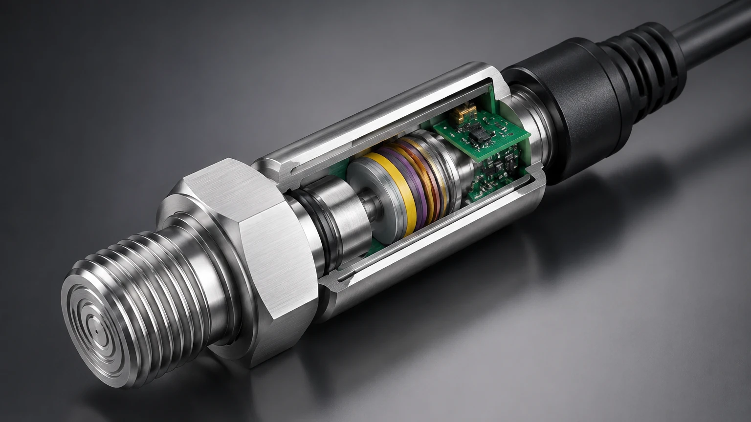
A detailed pressure transducer cross section reveals a multi-layered assembly designed to protect sensitive electronics while maintaining high sensitivity to external pressure changes. The internal structure can be divided into several functional zones.
1. The Process Interface (Wetted Parts)
At the base of the cross section is the diaphragm. This is the only part of the internal mechanism in direct contact with the process media. In a standard threaded transducer, the diaphragm may be recessed behind a small port, whereas in a flush-diaphragm design, it sits level with the process connection to prevent clogging in viscous or fibrous fluids.
2. The Transmission Medium
In many high-performance transducers, the sensing element is not in direct contact with the process. Instead, a thin metal diaphragm (often Stainless Steel 316L or Hastelloy) transfers pressure through an internal fill fluid—typically silicone oil or fluorinated oil—to the sensing chip. This "isolated" design protects the silicon chip from corrosive chemicals or moisture.
3. The Sensing Element (The Core)
Located deep within the housing, the sensing element is the heart of the device. In a piezoresistive cross section, you will see a silicon die bonded to a substrate. This die contains a Wheatstone bridge circuit etched into the material. When pressure is transmitted through the fill fluid, the die deforms slightly, changing the resistance of the bridge.
4. Signal Conditioning Electronics
Above the sensing element, the cross section reveals a Printed Circuit Board (PCB). This area contains the Application-Specific Integrated Circuit (ASIC) responsible for temperature compensation, linearization, and signal amplification. Without this stage, the raw millivolt signal from the sensor would be too weak and unstable for industrial use.
5. Housing and Sealing
The entire assembly is encased in a robust metal housing, typically 304 or 316L stainless steel. The cross section shows various O-rings (Viton, EPDM, or Nitrile) and laser-welded joints that prevent the ingress of environmental moisture (IP65 to IP68 ratings).
Material Selection and Housing Integrity
When reviewing a pressure transducer cross section, material compatibility is the most frequent point of failure in industrial applications. The "wetted materials" must be chosen based on the chemical properties of the fluid being measured.
* Stainless Steel 316L: The industry standard for water and mild chemicals.
* Ceramic (Al2O3): Excellent for abrasive slurries and highly corrosive acids where stainless steel might pit or corrode.
* Hastelloy C / Tantalum: Reserved for extreme chemical environments like concentrated sulfuric acid or chlorine.
Furthermore, the housing must provide adequate protection against atmospheric conditions. In submersible level applications, the cross section includes a specialized vented cable. This cable contains a small capillary tube that allows the internal side of the sensor to "breathe" to the atmosphere, ensuring that the measurement is compensated for changes in barometric pressure (gauge pressure measurement).
Technical Selection Table for Industrial Applications
Choosing the right internal configuration depends on the specific demands of the process. The following table compares common internal designs found in the Welk product line.
| Feature | Piezoresistive (Silicon) | Ceramic Thick-Film | Capacitive (Ceramic/Metal) |
| :— | :— | :— | :— |
| Sensitivity | Very High | Moderate | High |
| Overpressure Resistance | Moderate | High | Excellent |
| Chemical Resistance | Depends on isolation diaphragm | Naturally high | High |
| Long-term Stability | Good | Excellent | Superior |
| Typical Applications | Oil, Gas, Clean Water | Chemicals, Slurries | Low-pressure gas, Laboratory |
| Cross Section Complexity | High (requires fill fluid) | Low (dry cell) | Moderate |
For more detailed technical specifications and to Review product options and application support, engineers should consult the Main Page for specific model data sheets.
Installation and Maintenance Guidelines
The physical layout shown in a pressure transducer cross section dictates how the device should be installed to avoid premature failure.
Mounting Orientation
While most modern transducers can be mounted in any orientation, very low-pressure sensors may experience a "zero shift" if their orientation is changed after calibration. This is due to the weight of the internal fill fluid pressing against the diaphragm. Always zero the sensor in its final mounting position.
Pressure Port Protection
In the cross section of a non-flush transducer, there is a small cavity in front of the diaphragm. In water treatment applications, this cavity can trap silt or ice. If the fluid is likely to freeze, the expansion of ice within this small volume can easily rupture the diaphragm. In such cases, a flush-diaphragm model or heat tracing is required.
Electrical Connection
The top of the cross section usually features a DIN connector, an M12 plug, or a cable gland. Ensure that the bend radius of the cable is at least 10 times the cable diameter to prevent damage to the internal vent tube. If using a vented cable, the termination point must be in a dry junction box with a desiccant filter to prevent moisture from traveling down the vent tube into the electronics.
Limitations and Potential Failure Modes
Despite their robust construction, pressure transducers have finite operational limits. Understanding these through the lens of the pressure transducer cross section helps in predictive maintenance.
* Diaphragm Fatigue: Repeated pressure cycling can lead to work-hardening of the metal diaphragm, eventually causing cracks or a shift in the zero point.
* Temperature Drift: Although electronics compensate for temperature, extreme heat can change the viscosity and volume of the internal fill fluid, leading to measurement errors. Most industrial transducers are rated for -20°C to +80°C; higher temperatures require cooling siphons or remote seals.
* Overpressure Events: If the process pressure exceeds the "Proof Pressure" (typically 2x or 3x the rated range), the diaphragm will undergo permanent plastic deformation. The cross section will show a bowed diaphragm that no longer returns to its neutral state, resulting in a permanent offset in the signal.
Frequently Asked Questions (FAQ)
Q: What is the difference between a "dry" and "oil-filled" cross section?
A: A dry cross section (usually ceramic) has the sensing element directly exposed to the atmosphere or process (with a protective coating). An oil-filled cross section uses a secondary isolation diaphragm and silicone oil to transfer pressure to a silicon chip, providing better protection against moisture and contaminants.
Q: How does a flush diaphragm differ in a cross section view?
A: In a standard transducer, the diaphragm is recessed. In a flush design, the diaphragm is moved to the very front of the process connection, eliminating any cavities where food, polymers, or sludge could build up and harden.
Q: Can I use a standard pressure transducer for liquid level?
A: Yes, this is known as hydrostatic level measurement. By measuring the pressure at the bottom of a tank and knowing the liquid's density, the level can be calculated. You must ensure the transducer is either submersible or mounted at the lowest point of the tank.
Q: Why is the vent tube in the cable important?
A: For gauge pressure sensors, the vent tube ensures the back of the sensing diaphragm is exposed to current atmospheric pressure. This cancels out barometric changes, ensuring the sensor only measures the pressure of the process media.
For engineers and procurement professionals looking for reliable level and pressure measurement solutions, understanding these internal mechanics is the first step toward system optimization. Welk offers a wide range of customized OEM and ODM services to adapt these internal designs to specific industrial needs. To explore the full catalog, visit the Main Page for further information.