Pressure Transmitter 1 6
Pressure Transmitter 1 6
In industrial process control and automation, the pressure transmitter 1 6 (typically referring to a 1.6 MPa or 16 bar full-scale range) serves as a cornerstone for monitoring fluid dynamics and storage levels. Whether utilized in municipal water distribution, hydraulic systems, or chemical processing, selecting the correct pressure transmitter requires a deep understanding of measurement principles, media compatibility, and installation requirements. As a specialized manufacturer, Welk provides high-precision instruments designed to meet these rigorous industrial standards.
This guide explores the technical foundations of pressure transmitters with a 1.6 MPa range, their application in hydrostatic level measurement, and the critical factors engineering teams must consider during the procurement and installation phases.
Measurement Principles of Pressure Transmitters
Before selecting a pressure transmitter 1 6, it is essential to understand how these devices convert physical force into a standardized electrical signal. Most modern industrial transmitters utilize one of three primary sensing technologies.
Piezoresistive Sensing
Piezoresistive transmitters are among the most common for the 1.6 MPa range. They consist of a silicon diaphragm with integrated strain gauges. When pressure is applied, the diaphragm deforms, changing the electrical resistance of the gauges. This change is proportional to the pressure and is converted by internal electronics into a 4-20mA or 0-10V signal. These sensors are valued for their high sensitivity and stability in clean liquid and gas applications.
Ceramic Thick-Film Sensing
For more aggressive media, ceramic sensors are often preferred. A ceramic diaphragm moves slightly under pressure, changing the capacitance or resistance of a circuit. Ceramic is naturally resistant to corrosion and abrasion, making it ideal for wastewater or mildly acidic environments where a standard stainless steel diaphragm might fail.
Capacitive Sensing
Capacitive pressure transmitters measure the change in capacitance between a sensing diaphragm and a fixed reference electrode. These units are exceptionally robust and offer high accuracy and long-term stability, particularly in applications requiring high overpressure protection. They are frequently used in critical process industries where reliability is paramount.
The Role of Pressure Transmitters in Level Measurement
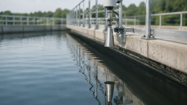
While pressure transmitters are designed to measure force per unit area, they are frequently employed as hydrostatic level sensors. In this context, the pressure transmitter 1 6 is used to determine the height of a liquid in an open or vented tank.
The Hydrostatic Principle
The relationship between pressure and liquid level is defined by the formula:
P = ρ × g × h
* P: Pressure (Pascals)
* ρ (Rho): Density of the liquid (kg/m³)
* g: Acceleration due to gravity (approx. 9.81 m/s²)
* h: Height of the liquid column (meters)
For a pressure transmitter 1 6 (1.6 MPa), the maximum measurable height for water (density ≈ 1000 kg/m³) is approximately 163 meters. This makes the 1.6 MPa range highly versatile for deep well monitoring, high-rise building water supply, and large industrial reservoirs.
When browsing the Main Page of a professional instrumentation supplier, you will find that these transmitters are often categorized by their mounting style—either submersible (dropped into the liquid) or externally mounted (connected via a pipe at the bottom of the tank).
Technical Selection Criteria for 1.6 MPa Transmitters
Choosing the right pressure transmitter 1 6 involves more than just matching the pressure range. Engineers must evaluate several technical parameters to ensure the device performs reliably in the field.
Accuracy Classes
Industrial transmitters are typically rated by their accuracy as a percentage of the Full Scale (FS). Common ratings include ±0.5% FS, ±0.25% FS, and ±0.1% FS. For a 1.6 MPa transmitter, a ±0.5% accuracy means a maximum error of 0.008 MPa. High-precision applications, such as custody transfer or laboratory testing, may require higher accuracy classes.
Output Signals and Communication
* 4-20mA (Analog): The industry standard, offering high noise immunity over long distances.
* 0-10V / 1-5V (Analog): Common in HVAC and simple PLC systems with short cable runs.
* RS485/Modbus (Digital): Allows for multiple sensors on a single bus and provides diagnostic data.
* HART Protocol: Superimposes a digital signal on the 4-20mA loop for remote configuration.
Material Compatibility
The wetted parts (the parts of the transmitter in contact with the media) must be compatible with the fluid. Standard options include:
* 304/316L Stainless Steel: Suitable for water, oil, and non-corrosive gases.
* Hastelloy C: Required for highly corrosive chemical applications.
* PTFE/Teflon Coatings: Used for strong acids or to prevent media adhesion.
Selection Table: Pressure Transmitter Technology Comparison
| Feature | Piezoresistive (Silicon) | Ceramic Thick-Film | Capacitive |
| :— | :— | :— | :— |
| Best For | Clean liquids, gases, high sensitivity | Corrosive media, abrasive fluids | High precision, high overpressure |
| Durability | Moderate | High | Very High |
| Standard Accuracy | 0.25% to 0.5% | 0.5% | 0.1% to 0.25% |
| Cost | Economical | Mid-range | Premium |
| Overload Capacity | 1.5x to 2x FS | 2x to 3x FS | Up to 10x FS |

Installation Considerations and Best Practices
Proper installation is critical to the longevity and accuracy of a pressure transmitter 1 6. Failure to follow engineering best practices can lead to signal drift, mechanical failure, or safety hazards.
Mounting Position
Transmitters should be mounted in a location that is easily accessible for maintenance but protected from extreme vibration. For liquid applications, the transmitter should ideally be mounted below the process tap to ensure the impulse line remains full of liquid, preventing air pockets that can cause erratic readings. Conversely, for gas applications, the transmitter should be mounted above the tap to allow condensate to drain back into the process line.
Environmental Protection
Ensure the transmitter's Ingress Protection (IP) rating matches the environment. For outdoor installations or areas subject to wash-downs, an IP65 or IP67 rating is standard. In hazardous areas where explosive gases or dust may be present, intrinsically safe (Ex ia) or flameproof (Ex d) certifications are mandatory.
Electrical Connections and Grounding
To prevent electromagnetic interference (EMI), use shielded twisted-pair cabling. The shield should be grounded at one end only (usually at the control cabinet) to avoid ground loops. Ensure the cable entry is sealed with a proper cable gland to prevent moisture from entering the housing through capillary action.
Pressure Snubbers
In systems prone to pressure spikes or water hammer (such as pump discharge lines), a pressure snubber should be installed. This device dampens sudden pressure surges that could otherwise rupture the sensing diaphragm of a 1.6 MPa transmitter.
Limitations and Common Risks
While the pressure transmitter 1 6 is a robust tool, it has specific limitations:
1. Temperature Extremes: Standard transmitters are usually rated for media temperatures between -20°C and +80°C. For steam or high-temperature oil, a cooling element or siphon must be used to protect the electronics.
2. Overpressure Events: Exceeding the 1.6 MPa range by a significant margin (usually >200%) can permanently deform the diaphragm, leading to a permanent zero shift or total failure.
3. Clogging: In wastewater or slurry applications, the small pressure port of a standard transmitter can become clogged. In these cases, a flush diaphragm design is required.
Frequently Asked Questions (FAQ)
Q: Can I use a 1.6 MPa transmitter for a system that normally operates at 1.5 MPa?
A: While technically possible, it is not recommended. It is best practice to select a range where the normal operating pressure is between 50% and 75% of the full scale. This provides a safety buffer for surges and ensures the sensor operates in its most linear region.
Q: What is the difference between Gauge Pressure and Absolute Pressure?
A: A gauge pressure transmitter (the most common type) measures pressure relative to atmospheric pressure. An absolute pressure transmitter measures relative to a perfect vacuum. For most level and process applications, gauge pressure is the standard.
Q: How often should a pressure transmitter 1 6 be calibrated?
A: For most industrial applications, an annual calibration check is sufficient. However, in critical processes or harsh environments, semi-annual calibration may be necessary to account for potential sensor drift.
Q: Does the orientation of the transmitter affect the reading?
A: On low-pressure ranges, orientation can cause a small zero shift due to the weight of the internal oil fill. For a 1.6 MPa transmitter, this effect is usually negligible, but it is still good practice to zero the instrument after it has been mounted in its final position.
Conclusion
The pressure transmitter 1 6 is a versatile and essential component in the modern industrial landscape. By understanding the underlying sensing technologies and adhering to strict installation protocols, engineers can ensure accurate data collection and long-term system reliability. Whether you are monitoring tank levels or controlling pipeline pressure, selecting a high-quality instrument from a reputable manufacturer like Welk is the first step toward process optimization.
For detailed product specifications and to explore our full range of level and pressure measurement solutions, please visit our Main Page. Our technical team is available to assist with custom configurations and OEM/ODM requirements to meet your specific application needs.