Rtd Transducer
Rtd Transducer
In the landscape of industrial automation and process control, the accurate measurement of temperature is as fundamental as the measurement of pressure or flow. An rtd transducer (Resistance Temperature Detector) serves as the bridge between a physical thermal state and a readable electronic signal. While often discussed in isolation, these devices are integral components in complex systems, including the advanced level measurement solutions provided by Welk. Understanding the mechanics, configurations, and selection criteria of RTD technology is essential for engineers tasked with maintaining process stability and safety.
Understanding the RTD Transducer: Principles of Operation
The fundamental principle behind an RTD is the predictable change in electrical resistance of certain metals in response to temperature changes. This is known as the Positive Temperature Coefficient (PTC) effect. As the temperature of the metal increases, the thermal agitation of the atoms increases, which in turn increases the resistance to electron flow.
Material Selection
While various metals can be used, platinum is the industry standard for high-precision RTD transducers due to its excellent linearity, wide temperature range, and chemical inertness. Other materials include nickel and copper, though these are typically reserved for specialized or lower-cost applications with narrower temperature bands. The most common configuration is the Pt100, which signifies a platinum element with a resistance of 100 ohms at 0°C.
The Role of the Transducer
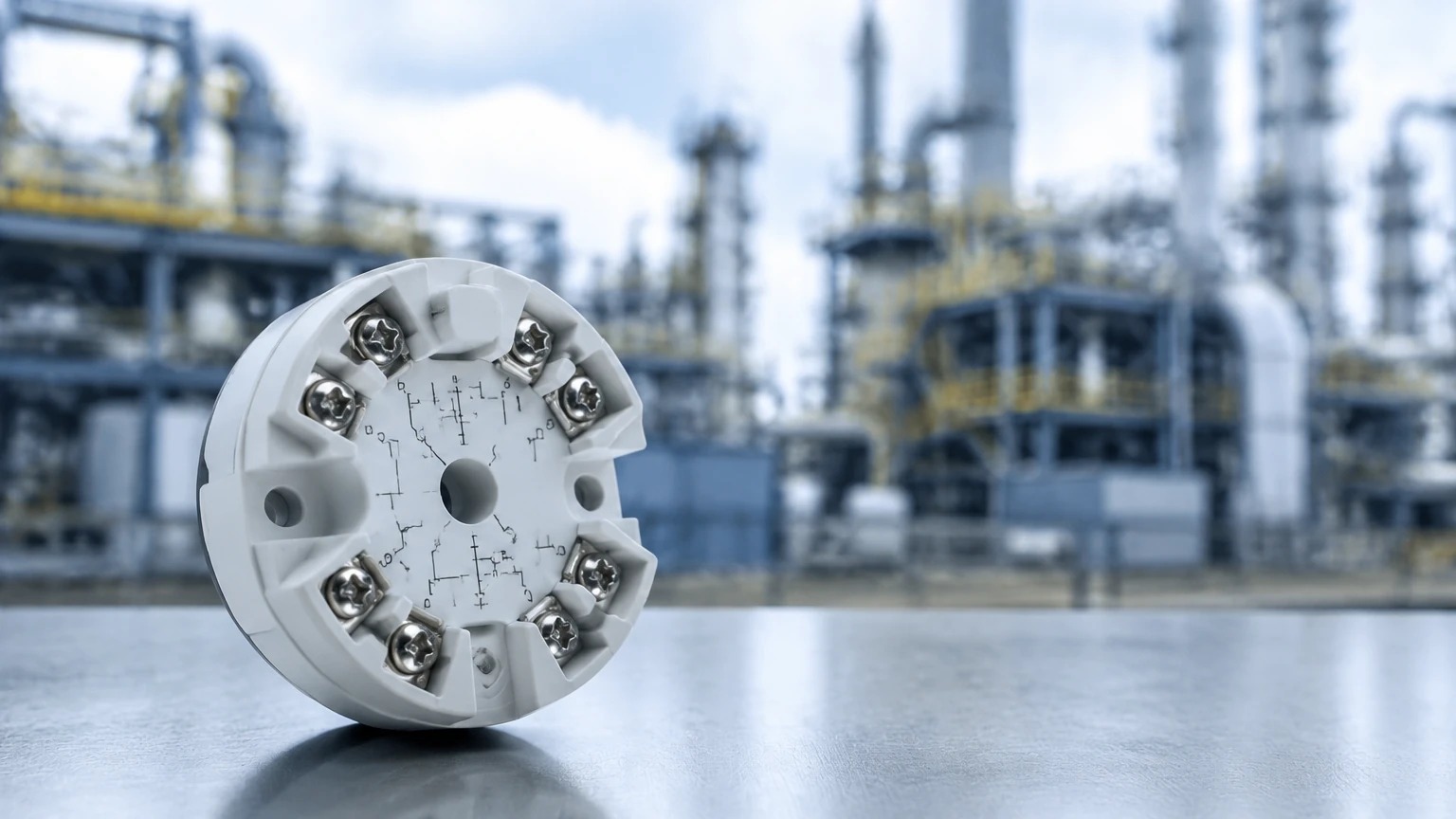
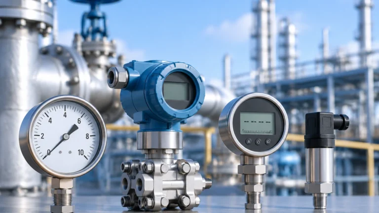
Technically, the RTD element itself is a primary sensor. The term "transducer" or "transmitter" refers to the electronic assembly that converts the raw resistance (measured in ohms) into a standardized industrial signal. In most modern facilities, this is a 4-20mA analog loop, though digital protocols such as HART, PROFIBUS, or Foundation Fieldbus are increasingly common. This conversion is vital because raw resistance signals are highly susceptible to electromagnetic interference (EMI) and signal degradation over long cable runs.
RTD Wiring Configurations and Lead Wire Compensation
One of the primary challenges in using an rtd transducer is the resistance of the lead wires connecting the sensor to the control system. Because the RTD measures small changes in ohms, the resistance of the copper wiring can introduce significant errors if not properly compensated. There are three primary wiring configurations used in industrial environments:
1. 2-Wire Configuration: This is the simplest and least expensive setup. However, the resistance of the lead wires is added directly to the sensor resistance, leading to a permanent positive offset in temperature readings. It is generally only suitable for applications where the receiver is very close to the sensor or where high precision is not required.
2. 3-Wire Configuration: This is the industrial standard. It utilizes a third wire to measure the lead resistance and subtract it from the total resistance. This assumes that all three wires have identical resistance, which is usually the case with high-quality multi-core cables. It provides a balanced compromise between cost and accuracy.
3. 4-Wire Configuration: Used primarily in laboratory settings or high-precision industrial processes, the 4-wire setup provides the highest level of accuracy. It uses two wires to carry the excitation current and two independent wires to measure the voltage drop across the RTD element. This completely eliminates the effect of lead wire resistance, regardless of cable length or temperature fluctuations along the cable run.
Signal Conditioning and Mounting Options
An rtd transducer can be housed in various ways depending on the installation environment and the proximity to the control room.
* Head-Mount Transmitters: These small, puck-shaped transducers are installed directly inside the connection head of the temperature probe. This is advantageous because it converts the sensitive resistance signal into a robust 4-20mA signal as close to the source as possible, minimizing noise pickup.
* DIN-Rail Mount Transmitters: These are located in a centralized control cabinet. The raw resistance signal travels from the field to the cabinet via shielded cables. This setup is easier to maintain and calibrate as the electronics are protected from harsh field conditions (e.g., extreme heat, vibration, or corrosive atmospheres).
* Field-Mount Transmitters: These are housed in rugged, often explosion-proof enclosures designed for the most demanding environments, such as oil refineries or chemical processing plants.
Selection Criteria for Industrial Applications
Selecting the right rtd transducer requires an evaluation of the specific process requirements. Engineers should consult the Main Page of their equipment provider to ensure compatibility between temperature sensors and other process instruments like level gauges.
| Feature | Pt100 | Pt1000 |
| :— | :— | :— |
| Base Resistance | 100 Ω at 0°C | 1000 Ω at 0°C |
| Sensitivity | 0.385 Ω/°C | 3.85 Ω/°C |
| Lead Wire Impact | High (requires 3 or 4 wires) | Low (can often use 2 wires) |
| Self-Heating Risk | Lower | Higher |
| Common Application | General Industrial Process | Battery-powered/HVAC |
Accuracy Classes
RTDs are categorized by accuracy classes according to international standards like IEC 60751.
* Class AA (1/3 DIN): Tolerance of ±(0.1 + 0.0017 |t|) °C.
* Class A: Tolerance of ±(0.15 + 0.002 |t|) °C.
* Class B: Tolerance of ±(0.3 + 0.005 |t|) °C.
The Relationship Between Temperature and Level Measurement
In many B2B industrial contexts, temperature measurement is not an end in itself but a critical input for other measurements. Welk’s expertise in level measurement highlights the necessity of integrated temperature data.
Hydrostatic Level Measurement
Hydrostatic pressure sensors determine the level of a liquid based on the pressure exerted by the liquid column. However, the density of a liquid changes with temperature. Without an accurate rtd transducer providing real-time temperature compensation, the calculated level will drift as the process fluid heats or cools. For instance, in oil storage, a temperature change of 10°C can result in a significant volume calculation error if density is assumed to be constant.
Ultrasonic Level Measurement
Ultrasonic sensors measure the time-of-flight of sound waves. The speed of sound in air is highly dependent on temperature (varying by approximately 0.6 m/s per degree Celsius). Most high-quality ultrasonic level transmitters include a built-in RTD or allow for an external rtd transducer input to adjust the distance calculation based on the ambient air temperature between the sensor and the liquid surface.
Radar Level Measurement
While radar waves are generally unaffected by air temperature, the dielectric constant of some materials can change with temperature. Furthermore, in high-temperature reactors, monitoring the temperature near the radar antenna is crucial for ensuring the longevity of the instrument's electronic components and gaskets.
Installation Best Practices and Considerations
To ensure the longevity and accuracy of an rtd transducer, several installation factors must be addressed:
1. Thermowell Usage: In pressurized or corrosive processes, the RTD should be installed inside a thermowell. This allows for the removal of the sensor for calibration or replacement without breaking the process seal. However, the use of a thermowell increases the response time of the sensor.
2. Immersion Depth: To avoid errors caused by heat conduction along the sensor sheath (stem conduction), the RTD must be immersed to a sufficient depth. A general rule of thumb is an immersion depth of at least 10 times the diameter of the sensor protection tube.
3. Vibration Dampening: RTD elements are more fragile than thermocouples. In applications with high vibration (e.g., near pumps or compressors), thin-film RTD elements or specialized vibration-resistant housings should be used.
4. Moisture Protection: Ingress of moisture into the connection head can cause shunting between terminals, leading to erratic readings. Using properly rated cable glands (IP67/IP68) and ensuring the cover is tightly sealed is mandatory.
Limitations of RTD Technology
Despite their high accuracy, rtd transducer systems have limitations:
* Temperature Range: Typically limited to -200°C to +600°C (up to 850°C for specialized platinum sensors). For temperatures exceeding this, thermocouples are preferred.
* Response Time: RTDs generally have a slower response time compared to thermocouples, particularly when installed in heavy thermowells.
* Self-Heating: The transducer must pass a small current through the RTD to measure resistance. This current generates a small amount of heat. If the excitation current is too high, it can artificially raise the sensor's temperature, leading to errors.
* Cost: RTD systems are generally more expensive than thermocouple systems due to the cost of platinum and the complexity of the signal conditioning electronics.
Maintenance and Calibration
Industrial standards often require annual or bi-annual calibration of temperature loops. This involves checking the rtd transducer against a NIST-traceable reference standard using a dry-block calibrator or a precision oil bath. Because RTD drift is usually predictable and linear, many modern transducers allow for "sensor-transmitter matching" (using Callendar-Van Dusen constants) to achieve system accuracies better than the standard class ratings.
Frequently Asked Questions (FAQs)
Q: Can I use a 2-wire RTD with a 3-wire transducer?
A: Yes, by jumping the two compensation terminals at the transducer. However, you will lose the lead-wire compensation benefit, and the accuracy will be reduced to that of a 2-wire system.
Q: How do I know if my RTD transducer has failed?
A: A common failure mode is an "open circuit" (infinite resistance) or a "short circuit" (zero resistance). Most smart transducers will drive their 4-20mA output to a specific upscale (e.g., 21.0mA) or downscale (e.g., 3.8mA) error level to alert the PLC/DCS of a sensor failure.
Q: Why choose an RTD over a thermocouple?
A: Choose an RTD when accuracy, repeatability, and long-term stability are more important than response speed or extreme temperature capability. RTDs are the preferred choice for custody transfer and precise chemical reactions.
Q: Does cable shielding matter for RTD transducers?
A: Yes, absolutely. Even though the transducer converts the signal to 4-20mA, the segment of wire between the RTD element and the transducer is highly sensitive to noise. Shielded twisted pair cabling should always be used, with the shield grounded at only one end (usually the control cabinet) to prevent ground loops.
For more information on integrating temperature sensors with industrial level measurement systems, please visit the Main Page to explore our full range of technical resources and product specifications.