Stilling Well
Stilling Well
In the field of industrial process control, achieving an accurate and stable level measurement is often complicated by the physical dynamics within a vessel. Turbulence, surface foam, internal obstructions, and rapid fluid movement can all degrade the performance of level sensors. A stilling well—also known as a surge pipe or a bypass chamber—is a critical mechanical component used to mitigate these challenges. By providing a protected environment for the sensor, it ensures that the measurement reflects the true liquid level rather than temporary surface disturbances.
This guide provides a comprehensive technical overview of stilling well design, its interaction with different measurement technologies, and the engineering considerations necessary for successful implementation in industrial environments.
Understanding the Role of a Stilling Well in Level Measurement
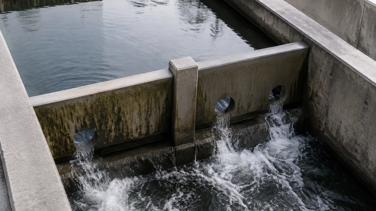
A stilling well is essentially a vertical pipe or chamber installed within a tank or vessel, or sometimes mounted externally. Its primary function is to isolate a portion of the process fluid from the broader turbulence of the tank. In vessels equipped with agitators, high-velocity inflow pipes, or chemical reactions that produce foam, the liquid surface is rarely flat.
Without a stilling well, non-contact sensors like radar or ultrasonic meters may receive scattered signals from waves or be unable to penetrate thick foam. Similarly, contact-based sensors like floats or hydrostatic transmitters can suffer mechanical stress or erratic readings due to the kinetic energy of moving fluid. The stilling well acts as a mechanical filter, allowing the liquid to enter through holes or slots at the bottom or along the sides, while damping the surface motion to create a "quiet" zone for the instrument.
Measurement Principles and Waveguide Physics
The effectiveness of a stilling well depends on how it interacts with the specific measurement technology employed. The physics of the well change based on whether the sensor uses sound waves, electromagnetic waves, or pressure.
Waveguide Effect in Radar Systems
For radar level meters, a stilling well acts as a waveguide. In an open tank, radar waves spread out in a cone. When these waves encounter a stilling well, they are confined within the pipe. This confinement prevents the signal from reflecting off tank walls, heating coils, or agitator blades. Furthermore, the waveguide effect concentrates the energy of the radar pulse, which significantly improves the signal-to-noise ratio, especially when measuring liquids with low dielectric constants (such as hydrocarbons).
Sound Damping in Ultrasonic Systems
Ultrasonic sensors rely on the time-of-flight of sound waves. Surface foam is a notorious problem for ultrasonic technology because it absorbs sound energy rather than reflecting it. A stilling well allows the foam to remain on the outside of the pipe while the liquid level inside remains clear, providing a solid surface for the sound pulse to bounce off. Additionally, the pipe protects the sensor from wind or air currents that could deflect the sound wave in outdoor applications.
Pressure Stabilization for Hydrostatic Sensors
For hydrostatic level transmitters, which measure the weight of the liquid column above the sensor, a stilling well prevents "noise" caused by fluid velocity (Bernoulli effect). In a fast-flowing or agitated tank, the localized pressure at the sensor face can fluctuate rapidly. The stilling well ensures that the sensor only experiences the static head pressure of the liquid.
Application with Radar Level Meters
Radar technology is perhaps the most common beneficiary of stilling well installations. When selecting a radar meter for use in a pipe, engineers must distinguish between guided wave radar (GWR) and non-contact (free-space) radar. For more detailed technical specifications on compatible sensors and their integration, you can Review product options and application support at the Welk Main Page.
Non-Contact Radar
In non-contact radar applications, the stilling well must be perfectly vertical and the interior surface must be smooth. Any burrs, weld beads, or misalignments inside the pipe can create "false echoes" that the radar might interpret as the liquid level. The pipe diameter must also be matched to the radar's frequency; generally, a larger diameter (100 mm or 4 inches) is preferred to minimize signal attenuation, though modern high-frequency radar (80 GHz) can operate effectively in much smaller pipes.
Guided Wave Radar (GWR)
While GWR uses a physical probe to guide the signal, it is often installed inside a stilling well (or bypass chamber) to provide mechanical protection and to isolate the probe from the turbulence of the tank. In this configuration, the stilling well acts as the outer conductor of a coaxial transmission line, which further enhances the signal strength and allows for the measurement of very low dielectric fluids.
Application with Ultrasonic and Hydrostatic Sensors
Ultrasonic Considerations
When using a stilling well with an ultrasonic sensor, the pipe must be large enough to prevent the "ringing" effect, where the sound wave reflects off the inner walls of the pipe too quickly for the sensor to process. A minimum diameter of 100 mm (4 inches) is typically recommended. It is also vital to ensure that the inner wall of the pipe remains free of moisture condensation or material buildup, as these can interfere with the acoustic signal.
Hydrostatic and Float Systems
For hydrostatic transmitters, the stilling well is often a simple PVC or stainless steel pipe with a series of small intake holes at the bottom. This design is particularly common in water treatment and reservoir monitoring. For float-based level switches or magnetic level gauges, the stilling well (or external chamber) ensures that the float moves strictly along a vertical axis without being tossed around by currents, which prevents mechanical jamming and premature wear.
Engineering Design and Material Selection
Designing a stilling well requires careful consideration of the process media and the vessel's physical constraints.
1. Material Selection: The well should be constructed from a material compatible with the process fluid. Stainless steel (316L) is the standard for chemical and oil applications due to its corrosion resistance. PVC, CPVC, or PTFE-lined pipes are used for highly corrosive acids.
2. Pipe Diameter:
* For Radar: Typically 50 mm to 200 mm (2" to 8").
* For Ultrasonic: Minimum 100 mm (4").
* For Hydrostatic: 50 mm (2") is usually sufficient.
3. Pipe Smoothness: For electromagnetic or acoustic sensors, the internal surface must be seamless. Longitudinal welds should be ground smooth to prevent signal interference.
4. Venting: This is the most critical design element. A stilling well must have a vent hole at the very top, above the maximum liquid level. This hole allows gas or air to escape as the liquid rises. Without a vent, the air trapped inside the pipe will compress, preventing the liquid from rising to the correct level and causing significant measurement errors.
Installation and Venting Requirements
Proper installation is the difference between a high-precision system and a failed one. Engineers should follow these guidelines:
* Verticality: The stilling well must be installed within 0.5° to 1° of true vertical. If the pipe is tilted, a radar signal may bounce off the side wall and never return to the sensor, or a float may drag against the side.
* Inlet Holes: To ensure the level inside the well matches the tank level, inlet holes or slots must be provided. For clean liquids, small holes at the bottom are sufficient. For viscous liquids or those with suspended solids, larger slots are required to prevent clogging.
* Stilling Well Bottom: The bottom of the pipe should ideally be open or have large drain holes to allow sediment to fall out. If the pipe rests on the bottom of the tank, ensure there is a gap for fluid entry.
* Venting Specifics: The vent hole should be approximately 3 mm to 6 mm in diameter. It must be positioned so that it cannot be plugged by splashing or condensation.
Selection Table for Stilling Well Components
| Feature | Radar (Non-Contact) | Ultrasonic | Hydrostatic | Magnetic Float |
| :— | :— | :— | :— | :— |
| Recommended Material | 316 SS / Alloy | PVC / 316 SS | PVC / 316 SS | 316 SS / Titanium |
| Min. Diameter | 50 mm (2") | 100 mm (4") | 50 mm (2") | Depends on Float Size |
| Internal Finish | Seamless / Polished | Smooth | Standard | Standard |
| Venting | Required (Top) | Required (Top) | Required (Top) | Required (Top) |
| Inlet Style | Slots or Holes | Large Holes | Small Holes | Large Holes/Open Bottom |
| Primary Purpose | Waveguide / Signal Gain | Foam / Turbulence | Turbulence Damping | Mechanical Stability |
Operational Limitations and Maintenance
While stilling wells solve many problems, they introduce specific risks that maintenance teams must monitor:
* Clogging and Scaling: In applications involving wastewater, crude oil, or crystallizing chemicals, the inlet holes or the pipe itself can become clogged. If the holes are blocked, the level inside the well will remain static even as the tank level changes, leading to dangerous overfills or dry runs.
* Buildup: For radar and ultrasonic sensors, material buildup on the inner walls of the pipe can create "ghost" echoes. Periodic cleaning or the use of specialized coatings may be necessary.
* Corrosion: Because the stilling well is a permanent internal fixture, its failure (e.g., a hole corroding through the side) can change the waveguide properties for radar, leading to measurement drift.
* Dielectric Limitations: While stilling wells help with low dielectric fluids, if the fluid's dielectric constant is extremely low (below 1.4), even a stilling well may not provide enough signal reflection for some older radar models.
Frequently Asked Questions
Q: Can I use a stilling well with an agitator in the tank?
A: Yes, this is one of the primary reasons to use a stilling well. It protects the sensor from the mechanical force of the moving liquid and the surface turbulence created by the blades.
Q: How do I calculate the vent hole size?
A: For most industrial tanks, a 6 mm (1/4") hole is sufficient. If the tank fills or empties at an extremely high rate, a larger vent may be needed to ensure no pressure differential develops between the pipe and the tank headspace.
Q: Does the stilling well need to reach the bottom of the tank?
A: It should ideally extend below the lowest point you intend to measure. If you only need to measure the top 2 meters of a 10-meter tank, the well only needs to cover that range, provided the bottom is designed to allow fluid entry and exit.
Q: Can I use a plastic stilling well for radar?
A: It is not recommended for non-contact radar because plastic does not reflect electromagnetic waves the same way metal does; it will not act as an effective waveguide. Metal pipes (or metal-lined pipes) are required for the waveguide effect.
Conclusion
The implementation of a stilling well is a proven engineering strategy for stabilizing level measurements in difficult process conditions. By understanding the specific requirements of the sensor technology—whether it be the waveguide needs of a radar meter or the damping needs of a hydrostatic transmitter—facilities can significantly improve the reliability of their automation systems. When designed with proper venting, material compatibility, and maintenance access, a stilling well transforms an erratic measurement environment into a controlled, high-precision process. For assistance in selecting the right instrumentation for your stilling well application, refer to the Main Page for expert guidance and product configurations.