Tank Level Alarm
Tank Level Alarm
In industrial process control, a tank level alarm is a critical safety and operational component designed to detect when the volume of a liquid or solid within a vessel reaches a specific threshold. These systems serve as the primary defense against overfills, which can lead to environmental contamination and equipment damage, as well as low-level conditions that may cause pump cavitation or process interruptions. Implementing a robust tank level alarm system requires a deep understanding of measurement physics, media characteristics, and the specific requirements of the storage environment.
For engineers and plant managers, selecting the right technology involves more than just choosing a sensor; it requires integrating reliable detection methods with effective signaling to ensure site safety. To explore the full range of industrial measurement solutions, technical professionals often refer to the Main Page of established manufacturers like Welk to compare performance specifications across different technologies.
Measurement Principles for Level Alarming
Level detection for alarm purposes generally falls into two categories: point level detection and continuous level measurement. Each relies on distinct physical principles to determine the presence or absence of material at a specific height.
Point Level Detection (Discrete Alarms)
Point level sensors are designed to trigger a signal only when the material reaches a fixed point. These are commonly used as "high-high" or "low-low" safety switches.
* Float Switches: These utilize a buoyant float containing a magnet. As the liquid level rises or falls, the float moves along a stem, actuating a reed switch. This is a mechanical principle suitable for clean, non-coating liquids.
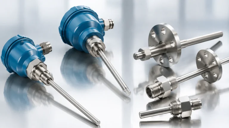
* Tuning Fork (Vibrating Level Switches): The sensor fork vibrates at its natural resonant frequency. When the fork is immersed in the medium, the frequency shifts. This change is detected by the electronics and converted into a switching signal. This method is highly resistant to turbulence and bubbles.
* Capacitance Switches: These measure the change in capacitance between the sensor probe and the tank wall. Since different materials have different dielectric constants, the arrival of the medium at the probe changes the electrical capacity, triggering the alarm.
Continuous Level Measurement (Integrated Alarms)
Continuous sensors provide a constant signal (typically 4-20mA or digital protocols) representing the exact level. Alarms are then programmed into the control system (PLC/DCS) based on the transmitter's data.
* Radar Level Meters: These devices emit high-frequency microwave pulses (typically 26GHz or 80GHz). The pulses reflect off the material surface and return to the antenna. The time-of-flight (ToF) is used to calculate the distance. Radar is non-contact and unaffected by temperature or pressure fluctuations.
* Ultrasonic Sensors: Similar to radar, these use sound waves. However, they are sensitive to air temperature and vapor composition, making them better suited for stable atmospheric conditions like water treatment tanks.
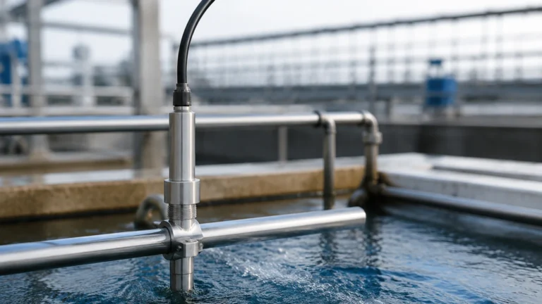
* Hydrostatic Pressure: This principle measures the pressure exerted by the liquid column at the bottom of the tank. The pressure is proportional to the height of the liquid and its density ($P = \rho gh$).
Critical Alarm Thresholds: High, Low, and Overfill
A standard industrial tank level alarm strategy typically involves four primary setpoints, often referred to as the "Level Safety High/Low" hierarchy.
1. High-High (HH): This is the overfill prevention level. When triggered, it usually initiates an emergency shutdown (ESD) of inlet pumps or valves to prevent a catastrophic spill.
2. High (H): This serves as an operational warning. It alerts the operator that the tank is reaching capacity and that the inflow should be diverted or reduced.
3. Low (L): This indicates that the tank is nearly empty. It is often used to trigger the start of a refill cycle or to alert operators to prepare for a changeover.
4. Low-Low (LL): This is a critical safety level designed to protect downstream equipment. For example, it will shut down discharge pumps to prevent them from running dry, which can cause mechanical seal failure or motor burnout.
Technical Selection Criteria
Selecting a tank level alarm system requires an evaluation of several technical variables. Failure to account for these can lead to false alarms or, more dangerously, a failure to trigger during a critical event.
Media Properties
* Dielectric Constant ($ε_r$): For radar and capacitance sensors, the reflectivity of the material is paramount. Low dielectric materials (like oils or liquified gases) reflect less energy than high dielectric materials (like water).
* Viscosity and Coating: Sticky or highly viscous fluids can coat sensor probes. In such cases, non-contact radar or vibrating forks with "coating rejection" capabilities are preferred.
* Density Variations: Hydrostatic sensors rely on constant density. If the liquid density changes due to temperature or chemical blending, the alarm setpoint will drift.
Tank Geometry and Environment
* Internal Obstructions: Agitators, heating coils, and ladders can create false echoes for ultrasonic and radar sensors. Advanced software filtering (false-echo suppression) is required.
* Vapor and Foam: Heavy foam can absorb ultrasonic signals and some radar frequencies. High-frequency 80GHz radar is generally more effective at penetrating light foam and focusing the beam to avoid obstructions.
Practical Selection Table
The following table provides a general guideline for matching alarm technologies with specific industrial applications.
| Technology | Best Application | Advantages | Limitations |
| :— | :— | :— | :— |
| Radar (Non-contact) | Chemical reactors, oil storage, corrosive acids | High accuracy, works in vacuum/high pressure | Higher initial investment |
| Ultrasonic | Water sumps, open channels, plastic tanks | Cost-effective, easy to install | Affected by wind, steam, and temperature |
| Vibrating Fork | Overfill prevention, pump protection | Maintenance-free, ignores bubbles/foam | Contact-based; not for heavy buildup |
| Hydrostatic | Vented tanks, deep wells, fuel storage | Simple, reliable for liquids with stable density | Requires contact with fluid; density sensitive |
| Magnetic Level Gauge | Boiler drums, high-pressure vessels | Visual indication + alarm switches | Mechanical moving parts; limited to liquids |
Installation and Integration Guidelines
Correct installation is as vital as the sensor technology itself. Even the most advanced tank level alarm will fail if positioned incorrectly.
Placement Considerations
* Avoid the Inflow: Never install a level sensor directly under a fill pipe. The turbulence and falling liquid will cause erratic readings and false alarms.
* Dead Zones (Blocking Distance): Every non-contact sensor has a "dead zone" near the antenna where measurement is impossible. Ensure the sensor is mounted high enough that the maximum liquid level does not enter this zone.
* Nozzle Geometry: For radar and ultrasonic units, the mounting nozzle should be short and wide enough to prevent the signal from reflecting off the nozzle walls.
Electrical Integration
In modern facilities, the tank level alarm is rarely a standalone buzzer. It is integrated into a broader automation framework:
* 4-20mA HART: Provides a continuous signal and diagnostic data.
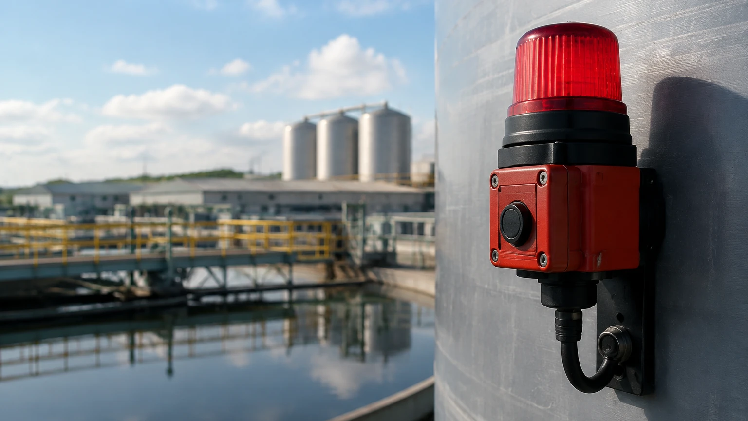
* Relay Outputs: Direct hard-wired connection to a pump starter or a siren for immediate action.
* Modbus/Profibus: Digital communication for large-scale tank farms where multiple sensors are networked to a single control room.
Common Risks and Troubleshooting
System reliability is often compromised by environmental factors that emerge after commissioning.
* Condensation: In humid environments, water droplets can form on the sensor face. While many Welk radar units feature drip-off designs, heavy condensation may still require the use of an air purge system to keep the antenna clear.
* Turbulence: Rapidly mixing tanks can cause the surface to fluctuate wildly. Using a stilling well (a pipe inside the tank) can provide a calm surface for the sensor to measure, ensuring a stable alarm signal.
* Signal Interference: In metal tanks, multiple reflections (multipath interference) can occur. Selecting a sensor with a narrow beam angle (e.g., 3° to 8°) minimizes this risk by focusing the energy on the product surface.
Frequently Asked Questions (FAQs)
1. Can one sensor provide both continuous measurement and high-level alarms?
Yes. A continuous transmitter (like a radar level meter) can have multiple alarm setpoints programmed into the PLC. However, for critical safety applications (SIL-rated), it is often a regulatory requirement to have a separate, redundant point-level switch (like a vibrating fork) as a dedicated overfill alarm.
2. How do I calibrate a tank level alarm for a pressurized vessel?
For pressurized vessels, non-contact radar is ideal because it is independent of vapor space pressure. If using hydrostatic sensors, you must use a differential pressure (DP) transmitter to subtract the top-side gas pressure from the total bottom pressure.
3. What is the maximum range for an ultrasonic tank level alarm?
Typically, ultrasonic sensors are effective up to 15 or 20 meters. Beyond this, the signal attenuation in air becomes too great, and radar technology is recommended for ranges up to 30, 70, or even 120 meters.
4. Are these systems suitable for hazardous areas?
Yes. Most industrial level alarms are available with Intrinsically Safe (Ex ia) or Flameproof (Ex d) certifications for use in explosive atmospheres common in the oil, gas, and chemical sectors.
Conclusion
Implementing an effective tank level alarm strategy is a foundational requirement for modern industrial operations. By selecting the appropriate measurement principle—whether it be the precision of radar or the simplicity of a float switch—and adhering to strict installation standards, facilities can significantly reduce the risk of accidents and process inefficiencies. For those in the planning stages of a project, consulting technical resources and reviewing product specifications on the Main Page of a specialized manufacturer is the most reliable way to ensure the chosen instrumentation meets the specific demands of the application.