Thermal Air Flow Meter
Thermal Air Flow Meter
In industrial process control and energy management, measuring the movement of gases is as critical as monitoring liquid levels or pressure. The thermal air flow meter, also known as a thermal mass flow meter, has emerged as a primary instrument for measuring the mass flow rate of air and other gases directly. Unlike volumetric flow meters that require additional pressure and temperature compensation, thermal instruments utilize the thermal properties of the fluid to provide accurate data, making them indispensable in compressed air monitoring, combustion control, and environmental emissions tracking.
Measurement Principles of Thermal Air Flow Meters
To select the right instrument for a B2B application, it is essential to understand the underlying physics. Thermal air flow meters operate based on the principle of heat transfer. Most modern industrial designs employ the "constant temperature differential" method, which involves two Resistance Temperature Detectors (RTDs) immersed in the flow stream.
The Two-Sensor Method
1. The Reference Sensor: This RTD measures the actual temperature of the gas (the ambient process temperature).
2. The Velocity Sensor: This RTD is heated to a specific, constant temperature above that of the reference sensor.
As air flows past the heated velocity sensor, molecules carry heat away from the surface—a process known as convective cooling. The rate of heat loss is directly proportional to the mass flow rate of the gas. To maintain the constant temperature differential between the two sensors, the instrument’s electronics must increase the electrical current to the velocity sensor. This electrical power consumption is then converted into a linear mass flow signal.
King’s Law and Mass Flow
The relationship between heat loss and flow is governed by King’s Law, which dictates that the heat transfer is dependent on the mass of the gas (density x velocity) rather than just its volume. This is why a thermal air flow meter provides a direct mass flow reading (e.g., kg/h or Nm³/h) without needing external computers to correct for changes in process pressure or temperature.
Key Components and Construction
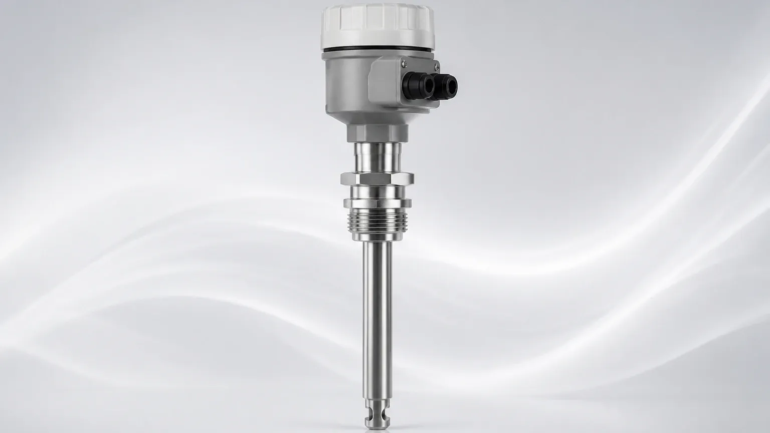
Industrial-grade thermal meters are built to withstand harsh environments. The probe is typically constructed from 316L stainless steel or Hastelloy to resist corrosion. The sensors themselves are often encapsulated in metal thermowells to protect them from particulate matter in the air stream.
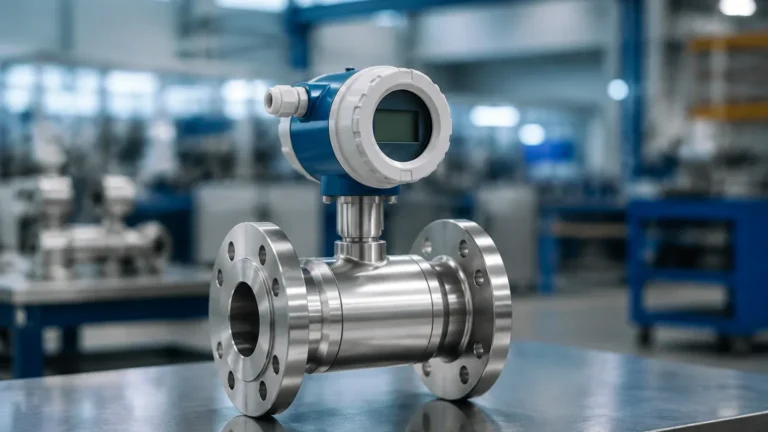
* Transmitter Electronics: Housed in an IP65 or IP67 rated enclosure, the electronics provide signal processing, local display, and communication outputs (4-20mA, Pulse, RS485/Modbus, or HART).
* Insertion vs. In-line Designs: Insertion meters are used for large pipe diameters (typically DN80/3" and above), allowing for installation through a ball valve. In-line meters include a built-in flow body and are preferred for smaller pipes (DN15 to DN50) where higher accuracy and flow conditioning are required.
Selection Criteria for Industrial Applications
Choosing a thermal air flow meter requires a detailed analysis of the process conditions. Engineers must evaluate the following factors to ensure long-term reliability and accuracy.
1. Gas Composition
Thermal flow meters are calibrated for specific gases because different gases have different thermal conductivities. While air is the most common, these meters are also used for nitrogen, argon, and carbon dioxide. If the gas composition changes significantly, the meter’s accuracy will drift unless it is recalibrated or features a multi-gas selection menu.
2. Flow Range and Turndown Ratio
One of the greatest strengths of thermal technology is its high turndown ratio, often reaching 100:1 or even 1000:1. This allows the meter to detect very low flow rates (leakage) as well as peak demand flows. When reviewing product options at the Main Page, it is vital to match the anticipated flow velocity (measured in Nm/s) with the meter’s calibrated range.
3. Pipe Size and Straight Run
For insertion meters, the depth of the probe must be calculated to ensure the sensors are at the point of average velocity (usually the center of the pipe). Furthermore, the flow profile must be fully developed, which requires specific lengths of straight pipe before and after the sensor.
Practical Selection Table
| Feature | Insertion Thermal Meter | In-line Thermal Meter |
| :— | :— | :— |
| Typical Pipe Size | DN80 to DN6000 (3" to 240") | DN15 to DN100 (1/2" to 4") |
| Installation Cost | Lower (single tap) | Higher (requires pipe cutting) |
| Accuracy | ±1.5% to 2.0% of reading | ±1.0% of reading |
| Pressure Drop | Negligible | Low to Moderate |
| Maintenance | Easy (can use hot-tap) | Requires process shutdown |
| Primary Use Case | Large ducts, stack gas, main air lines | Small process lines, gas mixing |
Installation Considerations
Proper installation is the most significant factor in the performance of a thermal air flow meter. Even the most advanced sensor will provide inaccurate data if the flow profile is turbulent or uneven.
* Straight Run Requirements: Standard installations generally require a minimum of 15 to 20 diameters (D) of straight pipe upstream of the meter and 5D downstream. If there are elbows, valves, or reducers closer than this, flow conditioners (honeycomb or perforated plates) may be necessary to stabilize the air stream.
* Orientation: In horizontal pipes, the probe should ideally be installed at the 2 o'clock or 10 o'clock position. This prevents moisture (which settles at the bottom) or debris from interfering with the sensors, while also avoiding air pockets that might collect at the very top.
* Moisture Control: Thermal meters are sensitive to water droplets. If the air is saturated (e.g., before a dryer in a compressed air system), droplets hitting the heated sensor will cause a sudden spike in the reading as the water absorbs a large amount of heat during evaporation. Always install these meters downstream of air dryers or in sections where the gas is above the dew point.
Limitations and Common Risks
While highly versatile, the thermal air flow meter is not a universal solution for every gas application. Understanding its limitations prevents costly specification errors.
1. Contamination and Coating: If the air contains oil mist or sticky particulates, a film can form over the RTD sensors. Since this film acts as an insulator, it reduces the heat transfer rate, leading to an under-reporting of flow. Regular cleaning or the use of self-cleaning cycles (if available) is necessary in dirty environments.
2. Changing Gas Mixtures: As mentioned, the calibration is gas-specific. In applications like biogas monitoring, where the ratio of Methane (CH4) to Carbon Dioxide (CO2) fluctuates, a standard thermal meter will lose accuracy unless it is equipped with a gas analyzer input or specialized compensation algorithms.
3. High-Temperature Limits: While some specialized versions can handle up to 400°C (750°F), standard thermal meters are typically limited to processes below 200°C (392°F) due to the limitations of the sensor potting materials and electronics.
Maintenance and Calibration
In B2B environments where flow data is used for billing or regulatory compliance, periodic calibration is mandatory. Most manufacturers recommend a factory calibration every 1 to 2 years.
* Field Verification: Some advanced meters offer "In-situ" calibration validation. This allows technicians to check the electronics and sensor integrity without removing the meter from the pipe. However, this does not replace a full NIST-traceable wind tunnel calibration.
* Cleaning: If the meter is used in a non-filtered air environment, the probe should be inspected every six months. Cleaning should be done with a non-abrasive solvent and a soft brush to avoid damaging the delicate RTD elements.
Frequently Asked Questions (FAQs)
Q: Can a thermal air flow meter measure steam?
No. Thermal mass flow meters are not suitable for steam due to the high moisture content and the phase-change nature of the fluid, which interferes with the thermal heat transfer principle. Vortex or differential pressure meters are better suited for steam.
Q: What is the difference between Normal (Nm³/h) and Standard (Sm³/h) units?
Both refer to mass flow corrected to a reference pressure and temperature. "Normal" typically refers to 0°C and 1.013 bar, while "Standard" often refers to 20°C or 15°C and 1.013 bar. It is crucial to confirm the reference conditions during the procurement phase to ensure the meter’s internal scaling is correct.
Q: Does the meter work in a vacuum?
Thermal meters require a minimum density of gas to transfer heat. While they can work in low-pressure environments, they are generally not recommended for high-vacuum applications where the mean free path of molecules is too large for effective convection.
Conclusion
The thermal air flow meter remains a top choice for industrial professionals due to its lack of moving parts, direct mass flow output, and exceptional sensitivity. By adhering to strict installation guidelines and ensuring the gas remains dry and clean, facilities can achieve highly accurate monitoring for years. For those integrating flow measurement with other process variables, exploring a wide range of industrial instrumentation at the Main Page can provide a holistic view of the available technologies for modern automation.