Time Constant Symbol in Physics
Time Constant Symbol in Physics
In the field of industrial automation and process control, understanding the temporal behavior of sensors is critical for maintaining system stability and accuracy. One of the most fundamental parameters used to describe this behavior is the time constant. Whether engineers are calibrating a radar level meter or configuring a hydrostatic transmitter, they must account for the delay between a change in the physical process and the corresponding change in the instrument's output. Central to this understanding is the time constant symbol in physics, which serves as the shorthand for a system's responsiveness.
The Definition and Symbol of the Time Constant
In physics and engineering, the time constant is a parameter that characterizes the response to a step input of a first-order, linear time-invariant (LTI) system. The time constant symbol in physics is the Greek letter tau ($\tau$).
Mathematically, for a system described by a first-order differential equation, the time constant represents the time it takes for the system's step response to reach approximately 63.2% of its ultimate final value. This value is derived from the expression $1 – e^{-1}$, where $e$ is the base of the natural logarithm (approximately 2.718). After a period of five time constants ($5\tau$), a system is generally considered to have reached its steady state, as it will have achieved 99.3% of its final value.
The Mathematical Foundation
To understand why the time constant symbol in physics is so prevalent, one must look at the standard equation for a discharging or charging system (such as a capacitor or a cooling body):
$$V(t) = V_0(1 – e^{-t/\tau})$$
Where:
- $V(t)$ is the value at time $t$.
- $V_0$ is the final steady-state value.
- $t$ is the elapsed time.
- $\tau$ is the time constant.
In industrial level measurement, this principle applies to the "damping" or "filtering" settings found in modern transmitters. For instance, when a Main Page for industrial level instruments is consulted, the technical specifications often list a "response time" or "damping constant," both of which are practical applications of the $\tau$ symbol.
Measurement Principles and System Response
Before selecting or installing a level meter, it is essential to understand how different measurement principles interact with the concept of the time constant. Industrial sensors do not provide instantaneous readings; they involve mechanical, electrical, and computational delays.
Electronic Damping and Signal Processing
In electronic level measurement, such as with radar or ultrasonic sensors, the raw signal often contains noise caused by surface turbulence, foam, or agitator blades. To provide a stable output (typically 4-20mA or a digital signal), the instrument applies a digital filter. This filter is essentially a software-based RC (Resistor-Capacitor) circuit where the user can define the time constant.
Increasing the time constant ($\tau$) smoothens the output but introduces lag. If a tank is filling rapidly, a time constant that is too high might cause the level meter to report a lower-than-actual level, potentially leading to an overfill condition.
Mechanical and Hydrostatic Response
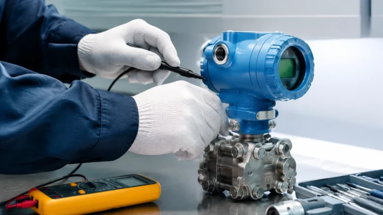
Hydrostatic level transmitters measure the pressure exerted by a liquid column. While the pressure change is nearly instantaneous, the physical construction of the sensor—including the diaphragm and the fill fluid—creates a mechanical time constant. In viscous fluids or at very low temperatures, the movement of the fill fluid can slow down, increasing the effective $\tau$ of the instrument.
Time Constant Applications Across Technologies
Different level measurement technologies have inherent response characteristics. Choosing the right one requires balancing the need for speed against the need for signal stability.
| Technology | Typical Inherent Response Time | Primary Source of Delay | Common Adjustment Range ($\tau$) |
| :— | :— | :— | :— |
| Radar (FMCW) | < 1 second | Signal processing/FFT calculation | 0 to 99 seconds |
| Ultrasonic | 1–5 seconds | Speed of sound and pulse averaging | 1 to 60 seconds |
| Hydrostatic | < 100 milliseconds | Diaphragm displacement | 0 to 30 seconds |
| Magnetic Level Gauge | 2–10 seconds | Float inertia and fluid viscosity | N/A (Mechanical) |
| Level Switches | < 500 milliseconds | Relay/Transistor actuation | Fixed or 0-10s delay |
Radar Level Meters
Guided wave radar (GWR) and non-contact radar use high-frequency electromagnetic pulses. The "time of flight" is measured in nanoseconds. However, the time constant symbol in physics remains relevant because the electronics must average multiple pulses to distinguish the true level from false echoes. In high-speed applications, such as small dosing tanks, the time constant must be kept low (e.g., $\tau < 1s$).
Ultrasonic Level Sensors
Ultrasonic sensors are widely used in water treatment. Because the speed of sound varies with temperature, these devices often incorporate temperature compensation. The calculation of this compensation and the filtering of environmental noise (like wind or rain) typically result in a longer default time constant compared to radar.
Practical Selection and Engineering Considerations
When specifying an instrument from a professional manufacturer like Welk, engineers should evaluate the process dynamics to determine the required time constant.
Step-by-Step Selection Guide
1. Identify the Maximum Rate of Change: Determine how fast the liquid level can rise or fall in meters per minute (m/min).
2. Determine Allowable Error: Calculate how much "lag error" the process can tolerate. Lag error is approximately equal to the Rate of Change multiplied by the Time Constant.
3. Evaluate Surface Conditions: If the surface is turbulent (e.g., due to an agitator), a longer time constant is necessary to prevent the output from "jittering."
4. Match to Control Loop: If the level meter is part of a PID (Proportional-Integral-Derivative) control loop, the instrument's time constant should generally be much smaller than the process time constant to avoid instability.
Installation Considerations
* Stilling Wells: Using a stilling well can mechanically dampen surface fluctuations, allowing for a smaller electronic time constant and faster response to true level changes.
* Mounting Location: For hydrostatic sensors, mounting the sensor away from turbulent inflow pipes reduces the need for high damping settings.
* Cable Length: In some analog systems, extremely long cable runs can introduce parasitic capacitance, slightly affecting the electrical time constant of the signal loop, though this is rare in modern 4-20mA systems.
Limitations and Risks
While the time constant symbol in physics represents a useful tool for stabilization, it has inherent limitations:
* Overshoot and Undershoot: In systems with high inertia, a long time constant can mask the approach of a setpoint, leading to the control system overshooting the desired level.
* Aliasing: If the sampling rate of the instrument is too slow relative to the process changes (a violation of the Nyquist criterion), the time constant cannot effectively recover the true signal.
* Safety Hazards: In emergency shutdown (ESD) applications, high damping is dangerous. Level switches used for high-high (HH) alarms should have a near-zero time constant to ensure immediate action.
Frequently Asked Questions (FAQ)
Q: What is the difference between response time and time constant?
A: In physics, the time constant ($\tau$) is the time to reach 63.2% of the final value. "Response time" is a broader term and often refers to the time required to reach 90% ($2.3\tau$) or 95% ($3\tau$) of the final value.
Q: How do I calculate the time constant for an RC circuit in a sensor?
A: The formula is $\tau = R \times C$, where $R$ is resistance in Ohms and $C$ is capacitance in Farads. In digital sensors, this is simulated via software algorithms.
Q: Can the time constant be changed in the field?
A: Yes, most modern digital level transmitters allow the user to adjust the damping or time constant via a local display, HART communicator, or PC software.
Q: Why is the symbol tau ($\tau$) used specifically?
A: While the exact historical origin is debated, tau is the Greek equivalent of 't', standing for 'temps' or 'time'. It has become the standardized time constant symbol in physics across international engineering communities.
Conclusion
Understanding the time constant symbol in physics and its practical implications is vital for any engineer involved in liquid level measurement. By correctly balancing the damping factor ($\tau$), operators can ensure that their Welk level meters provide data that is both stable enough for clear visualization and fast enough for accurate process control. For those looking to explore specific hardware options that offer adjustable response times for complex industrial environments, reviewing the technical data available on the Main Page of reputable manufacturers is the recommended next step in the procurement and design process.