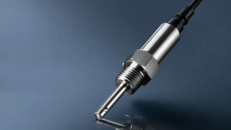
Ultrasonic Meters
Ultrasonic Meters
In the landscape of industrial automation, the ability to accurately monitor the volume or height of substances within a vessel is critical for operational efficiency and safety. Ultrasonic meters have emerged as a primary technology for non-contact level measurement. By utilizing high-frequency sound waves to determine the distance to a liquid or solid surface, these instruments provide a reliable solution for a diverse range of industries, including water treatment, chemical processing, and oil and gas. This guide provides a technical overview of ultrasonic level measurement principles, selection criteria, installation best practices, and the inherent limitations of the technology.
Measurement Principles of Ultrasonic Meters
Ultrasonic level meters operate on the "time-of-flight" (ToF) principle. The device consists of a transducer containing a piezoelectric crystal. When energized, this crystal vibrates at a specific frequency, emitting a pulse of ultrasonic sound waves—typically ranging from 20 kHz to over 200 kHz, which is well above the range of human hearing.
The Time-of-Flight Calculation
The emitted sound pulse travels through the air (or vapor space) until it strikes the surface of the process material. A portion of this energy is reflected back to the transducer, which now acts as a receiver. The internal electronics of the meter measure the exact time interval between the transmission of the pulse and the receipt of the echo.
The distance ($D$) between the sensor and the material surface is calculated using the following formula:
D = (c × t) / 2
Where:
- c is the speed of sound in the medium (typically air).
- t is the total time elapsed for the round trip.
Because the speed of sound in air is approximately 343 meters per second (m/s) at 20°C but varies significantly with temperature, most professional-grade ultrasonic meters, such as those provided by Welk, include an integrated temperature sensor to automatically compensate for these variations. Once the distance to the surface is known, the meter subtracts this value from the total tank height (the calibration distance) to determine the level of the material.
Why Choose Ultrasonic Technology?
Ultrasonic meters are favored in B2B industrial applications primarily due to their non-contact nature. Unlike hydrostatic transmitters or float-based systems, ultrasonic sensors do not touch the process media. This offers several distinct advantages:
1. Reduced Maintenance: Since there are no moving parts and no contact with potentially corrosive or viscous fluids, the risk of mechanical failure or sensor fouling is significantly minimized.
2. Versatility: These meters can measure both liquids and bulk solids, provided the surface is reflective enough to return an echo.
3. Cost-Effectiveness: Compared to radar level transmitters, ultrasonic meters generally offer a lower total cost of ownership for standard atmospheric applications.
4. Ease of Installation: Most units are top-mounted and can be configured via local displays or digital communication protocols without emptying the tank.
For engineers looking to integrate these systems into a broader automation framework, it is helpful to Review product options and application support to ensure the chosen hardware aligns with specific communication requirements like 4-20mA HART, Modbus, or Profibus.
Practical Selection Criteria
Selecting the correct ultrasonic meter requires a thorough understanding of the application environment. A "one-size-fits-all" approach often leads to signal loss or inaccurate readings. The following table outlines key selection parameters for common industrial scenarios.
Selection Table for Ultrasonic Level Meters
| Application Type | Recommended Frequency | Typical Range | Key Considerations |
| :— | :— | :— | :— |
| Small Chemical Tanks | High (70-100 kHz) | 0.25m – 6m | Chemical compatibility of transducer face (PVDF/PTFE). |
| Open Channel Flow | Medium (50-70 kHz) | 0.3m – 10m | High accuracy required; must support flume/weir calculations. |
| Large Water Reservoirs | Low (20-40 kHz) | 1m – 30m | High power needed to overcome signal attenuation over distance. |
| Bulk Solids/Grain | Very Low (<30 kHz) | 1m – 15m | Aiming flanges required; dust can attenuate high-frequency signals. |
| Sump/Lift Stations | Medium (50 kHz) | 0.5m – 12m | Submergence shields and condensation-resistant transducers. |
Key Evaluation Factors
* Measuring Range: The maximum distance the sound wave can travel and return. Note that signal strength decreases as the distance increases.
* Beam Angle: The conical spread of the ultrasonic pulse. A narrower beam angle (e.g., 5° to 10°) is preferable for narrow tanks or vessels with internal obstructions like agitators or ladders.
* Process Temperature and Pressure: Ultrasonic meters are generally limited to atmospheric or near-atmospheric pressure. High pressure increases the density of the gas, while vacuum conditions prevent sound waves from traveling at all.
* Accuracy and Resolution: Standard industrial units typically offer accuracy within 0.25% of the measured range.
Installation Considerations and Best Practices
Proper installation is the single most important factor in the long-term reliability of an ultrasonic meter. Even the most advanced signal processing cannot compensate for a poorly positioned sensor.
1. The Dead Zone (Blocking Distance)
Every ultrasonic transducer has a "dead zone" immediately below the sensor face—typically ranging from 0.2m to 0.8m depending on the frequency. Within this zone, the transducer cannot receive an echo because it is still vibrating from the transmission pulse. The maximum level of the material must never enter this dead zone.
2. Mounting Position
* Avoid the Center: In cylindrical tanks with domed tops, do not mount the sensor in the exact center, as this can create a "parabolic mirror" effect, focusing unwanted multiple echoes back to the sensor.
* Avoid the Wall: Mount the sensor at least 20-30 cm away from the tank wall to prevent the beam from hitting the side and causing false reflections.
* Perpendicular Alignment: The transducer face must be perfectly parallel to the surface of the liquid. A tilt of even a few degrees can cause the reflected signal to miss the receiver entirely.
3. Avoiding Obstructions
The ultrasonic beam spreads as it travels. Ensure that there are no internal pipes, ladders, or agitator blades within the beam's path. If obstructions are unavoidable, many modern meters feature "False Echo Suppression" software, which allows the user to map out and ignore static reflections from fixed internal structures.
Limitations and Environmental Challenges
While ultrasonic meters are highly versatile, they are not suitable for every environment. Engineering teams must be aware of the following limitations:
* Foam and Turbulence: Heavy foam on the surface of a liquid acts as an acoustic absorber, soaking up the sound energy and preventing an echo. Similarly, extreme turbulence can scatter the signal.
* Vapors and Gas Composition: If the tank contains a gas other than air (e.g., Nitrogen or Carbon Dioxide), the speed of sound will change significantly. If the gas concentration fluctuates, the meter will provide inaccurate readings unless the gas composition is constant and the meter is recalibrated for that specific medium.
* Vacuum Conditions: Sound requires a medium to travel. In a vacuum, ultrasonic measurement is impossible.
* High Temperature: Most ultrasonic transducers are limited to operating temperatures below 80°C (176°F) or 100°C (212°F). Beyond this, the piezoelectric elements can degrade, and the extreme temperature gradients in the air can distort the sound wave.
Comparison with Alternative Technologies
When evaluating ultrasonic meters, it is useful to compare them against other common level measurement technologies found on the Main Page of industrial catalogs:
* Radar (GWR or Non-Contact): Radar uses electromagnetic waves. It is unaffected by vacuum, dust, or temperature shifts but is generally more expensive than ultrasonic.
* Hydrostatic Transmitters: These measure the pressure exerted by the liquid column. They are excellent for deep wells but require contact with the fluid and are density-dependent.
* Magnetic Level Gauges: These provide a visual indication and are excellent for high-pressure/high-temperature bypass applications but involve mechanical floats that can get stuck.
Maintenance and Troubleshooting
Ultrasonic meters are largely maintenance-free, but periodic checks are recommended:
* Transducer Cleaning: In applications with high humidity or splashing, condensation or buildup can occur on the transducer face. Wipe the face with a soft cloth and mild detergent; do not use abrasive tools.
* Signal Strength Monitoring: Most digital meters provide a "Gain" or "Signal-to-Noise Ratio" (SNR) value. A sudden drop in signal strength may indicate the onset of foam or a misalignment of the sensor.
* Recalibration: If the process gas composition changes, the meter must be recalibrated to the new speed of sound.
Frequently Asked Questions (FAQ)
Q: Can ultrasonic meters measure the level of solids like sand or grain?
A: Yes, but with caveats. Solids often have an uneven surface that scatters the sound wave. Low-frequency sensors with higher power and aiming flanges are typically required for reliable solids measurement.
Q: How does wind affect an ultrasonic meter in an outdoor reservoir?
A: Strong wind can "blow" the sound pulse away from the receiver or create surface ripples that scatter the echo. In such cases, using a stilling well or a more powerful sensor can help.
Q: What is the difference between an ultrasonic transmitter and an ultrasonic switch?
A: An ultrasonic transmitter provides a continuous measurement (e.g., 4-20mA signal representing 0-100% level), while a switch only provides a discrete output (on/off) when a specific level is reached.
Q: Can I use an ultrasonic meter in a pressurized tank?
A: Most ultrasonic meters are designed for atmospheric pressure. While some can handle up to 3 bar (approx. 43 psi), radar is generally the preferred technology for high-pressure vessels.
By understanding these technical boundaries and following rigorous installation standards, industrial operators can leverage ultrasonic meters to achieve precise, low-maintenance level monitoring across a vast array of process applications.