Vega System
Vega System
In the landscape of industrial automation, a vega system represents a sophisticated approach to level, pressure, and point level detection. These systems are engineered to provide high-precision data in environments where accuracy is critical for safety, efficiency, and inventory management. Whether managing volatile chemicals, wastewater, or bulk solids, the integration of advanced sensors into a cohesive monitoring framework ensures that process operators can maintain continuous oversight of their assets.
Selecting the right instrumentation requires a deep understanding of the underlying physics of measurement. This guide explores the principles, selection criteria, and installation nuances of industrial level measurement systems, providing a technical foundation for engineers and procurement professionals.
Understanding Industrial Level Measurement Systems
An industrial level measurement system is rarely a standalone sensor. Instead, it is a networked solution comprising primary sensing elements, signal processing units, and communication interfaces. The term vega system often refers to the high-end integration of these components to handle complex process variables such as high temperatures, extreme pressures, and corrosive media.
For most B2B applications, the goal is to convert a physical level into a standardized electronic signal (such as 4-20mA, HART, or Modbus) that a Programmable Logic Controller (PLC) or Distributed Control System (DCS) can interpret. Achieving this reliably requires selecting a technology that matches the physical properties of the medium being measured.
Core Measurement Principles in Level Systems
Before specifying a system, it is essential to understand how different technologies interact with the process material. The most common principles used in modern industrial systems include Radar, Ultrasonic, and Hydrostatic measurement.
Radar Level Measurement (ToF)
Radar sensors utilize the Time-of-Flight (ToF) principle. The sensor emits a high-frequency microwave signal (typically in the 26 GHz or 80 GHz range) toward the product surface. The signal is reflected back to the sensor, and the system calculates the distance based on the time interval between emission and reception.
* FMCW (Frequency Modulated Continuous Wave): Modern systems often use FMCW radar, which emits a continuous signal with a changing frequency. This allows for higher precision and better signal-to-noise ratios, especially in vessels with internal obstructions.
* Advantages: Non-contact, unaffected by temperature or pressure fluctuations, and capable of penetrating vapors and dust.
Ultrasonic Level Measurement
Ultrasonic systems function similarly to radar but use sound waves instead of electromagnetic waves. A transducer emits an ultrasonic pulse that bounces off the surface of the medium.
* Speed of Sound Factor: Unlike radar, the speed of sound is affected by air temperature and gas composition. Therefore, ultrasonic sensors must include integrated temperature compensation to maintain accuracy.
* Advantages: Cost-effective for water and wastewater applications where the atmosphere is relatively stable.
Hydrostatic Pressure Measurement
This method calculates level based on the pressure exerted by a liquid column. The sensor measures the head pressure at the bottom of the tank. Using the formula *P = ρgh* (where P is pressure, ρ is density, g is gravity, and h is height), the system determines the liquid level.
* Advantages: Highly reliable for vented tanks and deep wells where non-contact sensors might struggle with signal reach.
Components of a Robust Level Monitoring System
A complete vega system involves several layers of hardware and software to ensure data integrity:
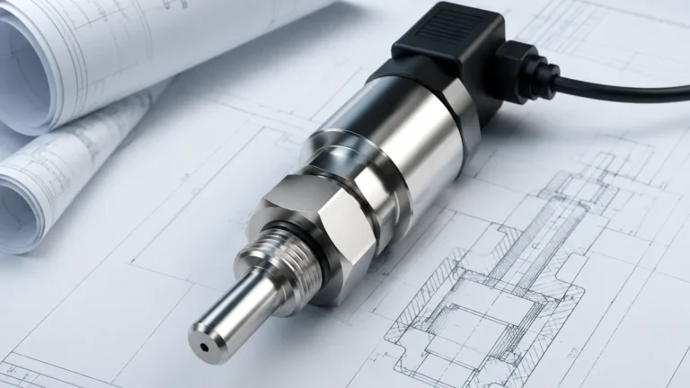
1. The Sensor/Transmitter: The primary device in contact with or facing the process. It must be constructed from materials compatible with the media (e.g., 316L Stainless Steel, PTFE, or PVDF).
2. Signal Processing Unit: Integrated electronics that filter out "false echoes" caused by agitators, ladders, or tank walls.
3. Communication Protocol: The method by which data is sent to the control room. While 4-20mA remains the standard, digital protocols like HART (Highway Addressable Remote Transducer) allow for remote diagnostics and calibration.
4. Local Display/HMI: Provides on-site technicians with real-time readings and configuration menus without needing a laptop.
For those looking to explore specific hardware configurations and technical specifications, the Main Page offers a detailed overview of industrial-grade transmitters designed for these integrated systems.
Selection Criteria for Industrial Level Sensors
Choosing the wrong technology can lead to frequent maintenance cycles or catastrophic process failures. Use the following criteria to evaluate your project requirements:
* Media Characteristics: Is the material liquid, solid, or slurry? What is its dielectric constant (for radar) or density (for hydrostatic)? Low dielectric materials like oils reflect radar signals more weakly than water-based liquids.
* Process Conditions: Operating temperatures can range from -40°C to over +200°C. Likewise, pressures can vary from vacuum to several hundred bars. Ensure the sensor housing and seal materials are rated for these extremes.
* Vessel Geometry: Tall, narrow silos may require narrow-beam 80 GHz radar to avoid wall interference, while open-air basins are better suited for ultrasonic or hydrostatic sensors.
* Accuracy Requirements: Custody transfer applications require millimeter-level precision, whereas simple pump control might only need ±1% accuracy.

Comparison Table: Level Measurement Technologies
| Technology | Best For | Max Range (Typical) | Key Limitation | Maintenance Level |
| :— | :— | :— | :— | :— |
| 80 GHz Radar | Complex tanks, chemicals | 120m | Higher initial cost | Very Low |
| 26 GHz Radar | Large silos, bulk solids | 70m | Sensitive to foam | Low |
| Ultrasonic | Water, wastewater | 15m | Affected by vapor/wind | Medium |
| Hydrostatic | Deep wells, vented tanks | 200m+ | Media density must be constant | Medium |
| Guided Wave Radar | Low dielectric liquids | 75m | Contact-based (buildup risk) | Medium |
Installation Guidelines and Best Practices
Proper installation is as important as the technology itself. Even the most advanced vega system will fail if the sensor is poorly positioned. Consider these engineering best practices:
Nozzle and Mounting Position
Sensors should be mounted away from the tank wall to prevent signal interference. For radar and ultrasonic sensors, the beam should not intersect the filling stream, as the falling material will create significant noise and false readings.
Dead Zones (Blocking Distance)
Every non-contact sensor has a "dead zone" directly beneath the transducer where measurements cannot be taken. Ensure the sensor is mounted high enough so that the maximum expected liquid level does not enter this zone.
Beam Angle and Obstructions
Calculate the beam spread based on the sensor’s frequency. If there are internal structures like cooling coils or agitators, the sensor must be positioned so the signal path is clear. In cases where obstructions are unavoidable, use the software’s "false echo suppression" feature to map out the static reflections.
Environmental Protection
For outdoor installations, use sunshades to prevent extreme temperature fluctuations from affecting the electronics. In hazardous areas (Class I, Div 1), ensure the system is installed with appropriate intrinsic safety barriers or explosion-proof housings.
Limitations and Operational Risks
While modern systems are highly robust, certain conditions present ongoing challenges:
* Heavy Foam: Thick, dense foam can absorb radar and ultrasonic signals, leading to a "loss of echo" error. In these scenarios, guided wave radar or hydrostatic sensors are often preferred.
* Vapor and Condensation: While radar can see through most vapors, heavy condensation on the sensor face can attenuate the signal. Sensors with PTFE drip-off antennas are designed to mitigate this.
* Dust and Build-up: In solids applications, dust can coat the sensor face. Some systems include air purge connections to keep the antenna clean during operation.
Frequently Asked Questions (FAQ)
Q: How often does a radar level transmitter need calibration?
A: Unlike mechanical gauges, radar transmitters have no moving parts and rarely drift. However, many industry standards (like ISO) recommend a functional check every 12 to 24 months to ensure the electronics and signal processing remain accurate.
Q: Can a vega system measure interface levels (e.g., oil on top of water)?
A: Yes, Guided Wave Radar (GWR) is particularly effective for interface measurement. The signal reflects off the upper layer (low dielectric) and continues through to reflect off the lower layer (high dielectric), allowing the system to calculate both levels.
Q: What is the difference between 26 GHz and 80 GHz radar?
A: The primary difference is the beam angle. 80 GHz radar has a much narrower beam, which makes it easier to install in small nozzles or tanks with many internal obstructions. It also provides better resolution for measuring thin layers.
Q: Are ultrasonic sensors suitable for vacuum tanks?
A: No. Ultrasonic waves require a medium (air or gas) to travel. In a vacuum, there is no medium to carry the sound, rendering the sensor non-functional. Radar is the preferred choice for vacuum applications.
For technical support in selecting the appropriate instrumentation for your specific industrial environment, visiting the Main Page can provide access to expert consultation and product comparisons tailored to global engineering standards.