Vortex Flowmeter
Vortex Flowmeter
In the landscape of industrial process control, the vortex flowmeter stands as one of the most versatile and reliable instruments for measuring the volumetric flow rate of liquids, gases, and steam. Based on the principle of vortex shedding, these meters are favored for their lack of moving parts, high durability, and wide rangeability. For engineers and facility managers, understanding the nuances of vortex technology is essential for optimizing system efficiency and ensuring the longevity of the instrumentation suite.
This guide provides a comprehensive technical overview of vortex flowmeters, detailing their operational physics, selection criteria, and the critical installation factors that influence performance in demanding B2B environments.
Understanding the Von Kármán Vortex Street Principle
The operation of a vortex flowmeter is rooted in a fluid dynamics phenomenon known as the Von Kármán effect. When a fluid—whether liquid, gas, or saturated steam—encounters an unstreamlined object (referred to as a bluff body or shedder bar) placed perpendicular to the flow stream, it cannot follow the contours of the object on both sides simultaneously.
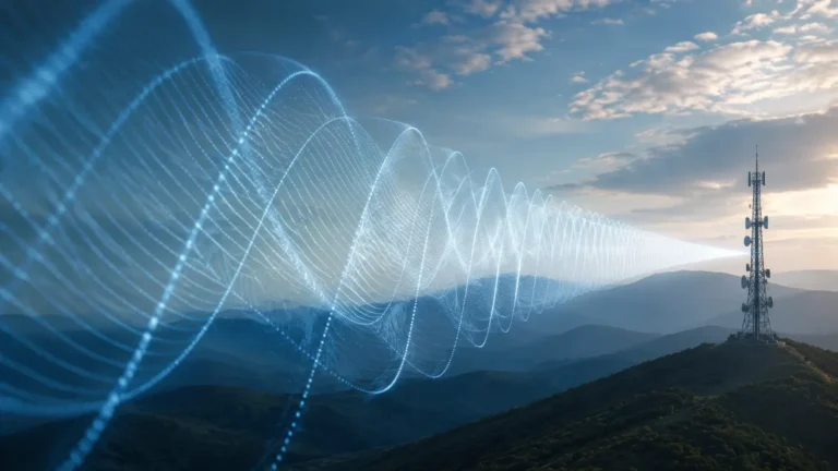
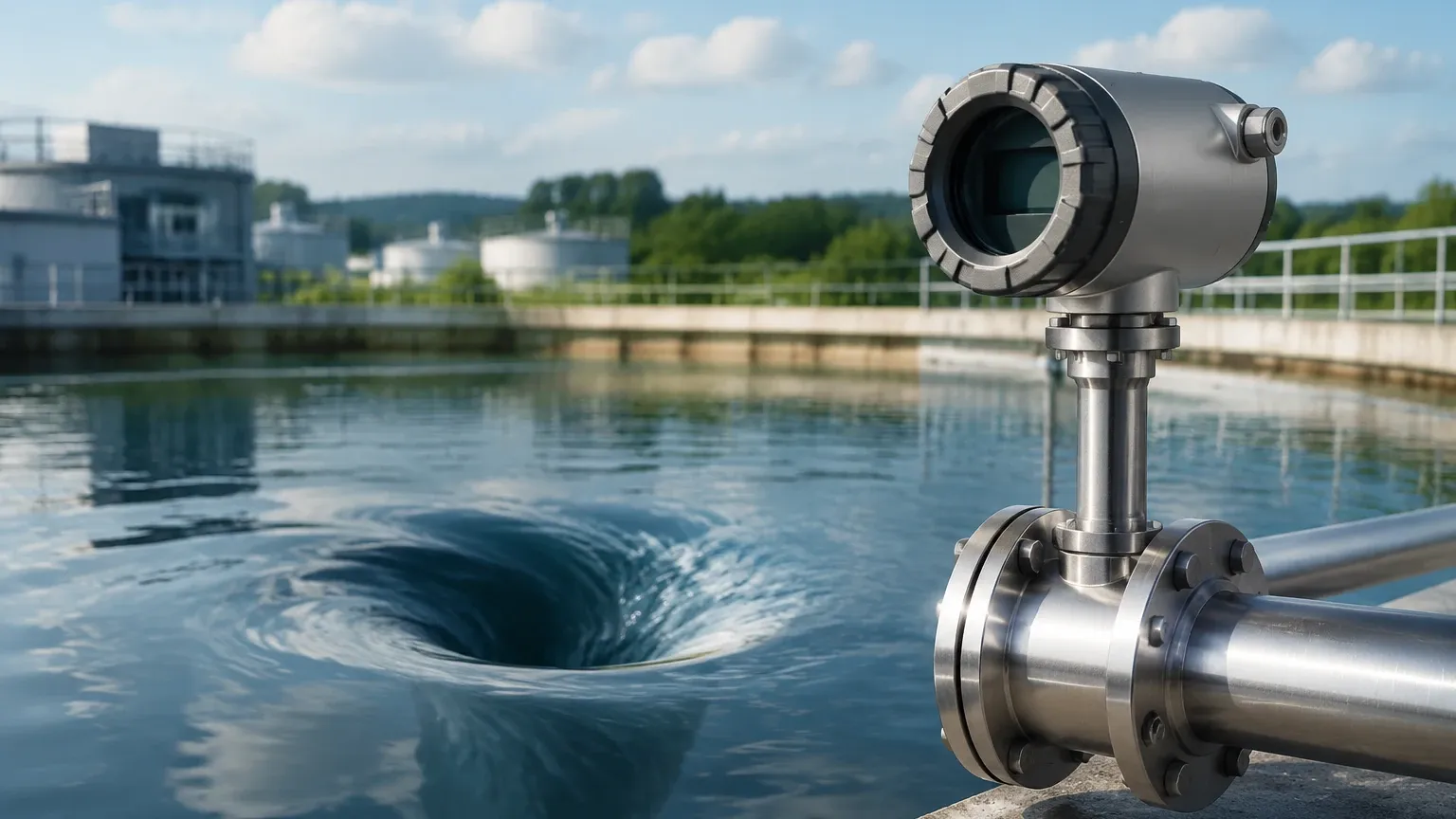
As the fluid passes the bluff body, it separates and creates alternating areas of high and low pressure, resulting in the formation of vortices (eddies) on trailing edges. These vortices are shed alternately from one side of the body to the other. The frequency at which these vortices are shed is directly proportional to the velocity of the fluid moving through the pipe.
The fundamental relationship is expressed by the formula:
f = St × (V / d)
Where:
* f is the frequency of vortex shedding (Hz).
* St is the Strouhal number (a dimensionless constant specific to the shape of the bluff body).
* V is the velocity of the fluid (m/s).
* d is the width of the bluff body (m).
Because the width of the shedder bar and the Strouhal number remain constant over a wide range of Reynolds numbers, the frequency becomes a highly linear representation of the flow velocity. This frequency is typically detected by a piezoelectric crystal or an ultrasonic sensor embedded within or behind the shedder bar, which converts the mechanical pressure pulses into electrical signals for the flow transmitter.
Types and Configurations of Vortex Flowmeters
Vortex flowmeters are categorized based on their mechanical construction and their ability to process secondary variables like temperature and pressure.
In-line Vortex Flowmeters
These are the most common types, where the meter body is flanged or sandwiched (wafer-style) directly into the piping. They provide high accuracy and are calibrated at the factory for specific pipe diameters, typically ranging from 15 mm to 300 mm (1/2" to 12").
Insertion Vortex Flowmeters
For very large pipelines (above 300 mm), insertion meters are often used. These involve a probe containing the shedder bar and sensor inserted into the pipe through a mounting nipple. While slightly less accurate than in-line models due to profile variations in large pipes, they offer significant cost savings and can often be installed via "hot tapping" without shutting down the process.
Multivariable Vortex Flowmeters
Standard vortex meters measure volumetric flow. However, in steam and gas applications, the density of the medium changes with temperature and pressure. Multivariable models include an integral temperature sensor (RTD) and sometimes a pressure transducer. This allows the onboard electronics to calculate mass flow in real-time, which is critical for energy balancing and custody transfer.
Technical Selection Criteria and Specification Table
Selecting the correct vortex flowmeter requires a deep dive into the process conditions. Unlike differential pressure meters, vortex meters have a "low-flow cutoff." If the fluid velocity is too low, the inertial forces are insufficient to form detectable vortices.
When evaluating options, engineers should reference the following selection parameters:
| Feature | Specification / Requirement |
| :— | :— |
| Fluid State | Liquids (low viscosity), Gases, Saturated/Superheated Steam |
| Reynolds Number (Re) | Minimum 5,000 to 20,000 for linear output |
| Accuracy (Liquid) | ±0.75% to ±1.0% of rate |
| Accuracy (Gas/Steam) | ±1.0% to ±1.5% of rate |
| Repeatability | ±0.2% |
| Temperature Range | -200°C to +400°C (depending on sensor type) |
| Pressure Rating | Up to 100 bar (standard), higher for custom builds |
| Turndown Ratio | Typically 10:1 to 30:1 |
| Material Compatibility | 316 Stainless Steel, Hastelloy, or Carbon Steel |
Reynolds Number Considerations
The Reynolds number is a dimensionless value representing the ratio of inertial forces to viscous forces. For a vortex flowmeter to operate accurately, the flow must be turbulent. If the fluid is too viscous (e.g., heavy oils), the vortices will not shed consistently, leading to measurement failure. Generally, vortex meters are not recommended for fluids with a viscosity exceeding 10 cP (centipoise).
Critical Installation and Piping Requirements
The accuracy of a vortex flowmeter is heavily dependent on the velocity profile of the fluid as it reaches the shedder bar. Disturbed flow caused by valves, elbows, or pumps can introduce swirl or turbulence that interferes with vortex formation.
Straight Pipe Runs
To ensure a stable flow profile, standard installations require a specific length of straight pipe upstream and downstream of the meter:
* Upstream: Minimum 10D to 40D (where D is the pipe diameter), depending on the presence of upstream obstructions like 90° elbows or pressure reducers.
* Downstream: Minimum 5D.
If the required straight runs cannot be achieved due to space constraints, a flow straightener or conditioner must be installed upstream of the meter.
Orientation and Piping Support
* Horizontal vs. Vertical: Vortex meters can be installed in any orientation. However, for liquid applications, the pipe must remain completely full. In vertical lines, the flow should always be upward to prevent air pockets.
* Vibration: Because the sensors detect pressure pulses, excessive piping vibration can be misinterpreted as flow. Meters should be installed in sections of pipe that are well-supported and away from high-vibration equipment like reciprocating compressors.
* Gasket Alignment: Ensure that gaskets do not protrude into the flow stream, as this can create parasitic vortices that degrade accuracy.
Limitations, Risks, and Environmental Factors
While robust, vortex flowmeters are not a "one-size-fits-all" solution. Identifying potential risks early in the project phase prevents costly downtime.
1. Cavitation in Liquids: If the pressure at the meter drops below the vapor pressure of the liquid, bubbles will form (cavitation). This not only damages the shedder bar but also makes accurate measurement impossible. Always ensure the system pressure is high enough to prevent flashing.
2. Pulsating Flow: If the process involves a pump or compressor that creates rapid pulsations, the vortex shedding frequency may "lock in" to the pulsation frequency, leading to significant errors.
3. Abrasive Media: While the lack of moving parts reduces wear, highly abrasive slurries can eventually erode the sharp edges of the shedder bar. This changes the Strouhal number and causes the meter to drift out of calibration.
4. Low Velocity Limits: In steam systems, particularly during low-demand periods (e.g., summer heating loads), the flow may drop below the meter's detectable limit. In these cases, a smaller diameter meter with reducers may be necessary to increase velocity.
Complementary Technologies: Level and Flow Integration
In many B2B industrial applications, flow measurement is only one part of a larger process control strategy. For instance, in boiler feed water systems or chemical storage tanks, flow data from a vortex flowmeter is often used in conjunction with level measurement data to perform mass balance calculations and leak detection.
While vortex meters track the movement of media through the system, instruments such as radar level meters, ultrasonic sensors, and hydrostatic transmitters monitor the inventory within vessels. Integrating these data points allows for automated replenishment and safety shut-off protocols. For organizations looking to optimize their entire measurement loop, consulting a specialized manufacturer is often the most efficient path. You can Review product options and application support to see how various level and flow technologies integrate into a cohesive automation architecture.
Frequently Asked Questions (FAQ)
Can a vortex flowmeter measure multi-phase flow?
No. Vortex flowmeters are designed for single-phase fluids. A mixture of liquid and gas (such as wet steam or aerated water) will cause erratic shedding and unreliable readings. For steam, ensure a steam trap is installed upstream to remove condensate.
How often does a vortex flowmeter need calibration?
Because there are no moving parts to wear out, vortex meters are extremely stable. In clean service, recalibration may only be required every 2 to 5 years. However, in corrosive or high-temperature steam service, annual verification is recommended.
What is the difference between a vortex meter and a turbine meter?
Turbine meters use a rotating rotor and are generally more accurate for clean liquids at very high pressures. However, they have moving parts that can wear or be damaged by debris. Vortex meters are more durable and better suited for steam and dirty gases where a turbine would fail.
Does the meter require a specific pressure to work?
While the meter has a maximum pressure rating, the "minimum" pressure is determined by the fluid's density. For gases and steam, if the pressure is too low, the fluid may not be dense enough to trigger the piezoelectric sensor at low velocities.
Is it possible to repair a vortex sensor in the field?
In many modern designs, the sensor element is isolated from the process (non-wetted), allowing it to be replaced without breaking the process seal or shutting down the line. Always check the manufacturer's specifications for "dry-replacement" capabilities.