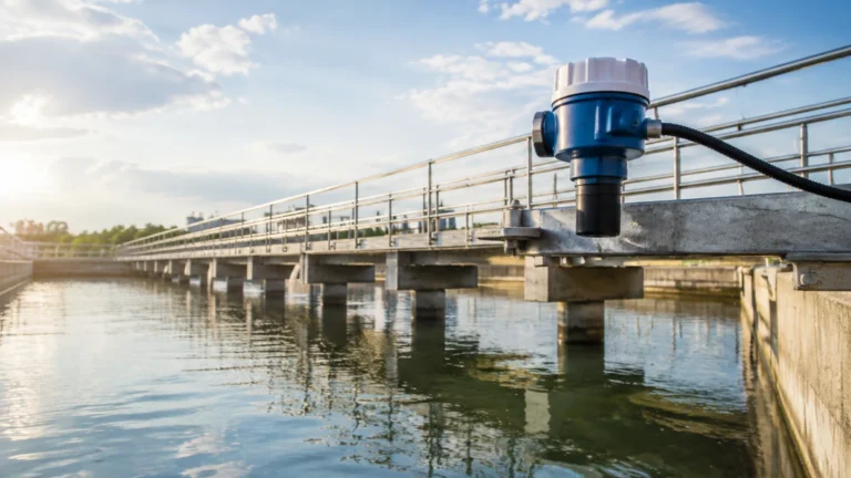
Water Level Sensor for Water Tank
Water Level Sensor for Water Tank
In industrial and municipal water management, the selection of a water level sensor for water tank applications is a critical engineering decision. Whether managing potable water storage, industrial process water, or wastewater treatment, the accuracy and reliability of level data directly impact operational efficiency, safety, and cost control. Modern level measurement technology has evolved from simple mechanical floats to sophisticated electronic sensors capable of millimeter-precision and remote integration.
Selecting the appropriate technology requires a deep understanding of the physical properties of the liquid, the geometry of the tank, and the environmental conditions of the installation site. This guide provides a technical overview of the primary measurement principles, selection criteria, and installation best practices for engineers and facility managers. For a comprehensive overview of available industrial instrumentation, technical specifications can be found on the Main Page.
Measurement Principles for Water Level Sensing
To choose the right water level sensor for water tank monitoring, one must first understand the physics behind the various sensing methods. Each principle offers specific advantages depending on whether the application requires continuous monitoring or point-level detection.
Hydrostatic Pressure Level Measurement
Hydrostatic sensors operate on the principle that the pressure at a specific point in a static liquid is proportional to the height of the liquid column above it. The formula used is $P = \rho \times g \times h$, where $P$ is pressure, $\rho$ is the density of the water, $g$ is gravity, and $h$ is the height of the liquid.
In practical applications, a submersible pressure transmitter is lowered to the bottom of the tank. It measures the pressure exerted by the water column and converts it into an electrical signal (typically 4-20mA). These sensors often include a vented cable to compensate for atmospheric pressure changes, ensuring that the measurement reflects only the liquid's weight. They are highly reliable for deep tanks and reservoirs but require the density of the liquid to remain relatively constant.
Ultrasonic (Non-Contact) Measurement
Ultrasonic sensors utilize the "time-of-flight" principle. The sensor, mounted at the top of the tank, emits high-frequency sound pulses. These pulses travel through the air, reflect off the water surface, and return to the sensor. The distance is calculated based on the time elapsed and the speed of sound in air.
Because ultrasonic sensors do not touch the liquid, they are ideal for applications where the water may contain corrosive chemicals or suspended solids that could damage contact-based probes. However, they are sensitive to temperature fluctuations (which change the speed of sound) and can be affected by heavy foam or steam on the water surface.
Radar Level Measurement
Radar sensors also use time-of-flight but employ electromagnetic waves (microwaves) instead of sound. Radar technology, particularly 26GHz and 80GHz high-frequency radar, offers superior precision. Unlike sound waves, microwaves are unaffected by air temperature, pressure, or vacuum conditions. Radar is the preferred choice for high-accuracy industrial water tanks where steam, dust, or slight surface agitation may be present.
Magnetic Level Gauges and Switches
Magnetic level gauges consist of a bypass chamber mounted to the side of the tank. Inside, a float containing a permanent magnet moves with the water level. Externally, magnetic flags or a transmitter track the float's position. This provides both a local visual indication and a remote signal. For simple high/low alarms, magnetic float switches are often used as redundant safety measures to prevent tank overfills.
Selection Criteria for Tank Level Sensors
When evaluating a water level sensor for water tank integration, engineers must consider several variables to ensure long-term performance. The following table summarizes the primary technologies and their typical application envelopes.
| Technology | Accuracy | Typical Range | Best Use Case | Limitations |
| :— | :— | :— | :— | :— |
| Hydrostatic | ±0.1% to 0.5% | 1m to 200m | Deep wells, vented tanks, reservoirs | Sensitive to density changes |
| Ultrasonic | ±0.25% of range | 0.3m to 15m | Open tanks, wastewater, chemical storage | Affected by foam and heavy steam |
| Radar | ±1mm to 3mm | 0.1m to 30m+ | Process water, high-precision storage | Higher initial cost |
| Magnetic Gauge | ±5mm to 10mm | 0.5m to 6m | Visual monitoring, side-mount needs | Moving parts subject to wear |
| Float Switch | N/A (Point) | Fixed | Overfill protection, pump control | No continuous level data |
Key Evaluation Factors
1. Tank Geometry: Tall, narrow tanks may favor hydrostatic or radar sensors. Tanks with internal obstructions (ladders, agitators) may require radar with "false echo suppression" or guided wave radar.
2. Media Characteristics: Pure water is easy to measure, but wastewater or gray water with high solids content may require non-contact sensors to prevent clogging or sensor coating.
3. Environmental Conditions: Outdoor tanks are subject to extreme temperature shifts. Ultrasonic sensors for these applications must have integrated temperature compensation.
4. Output Requirements: Most industrial systems require a 4-20mA signal, but modern smart tanks often utilize digital protocols like Modbus RTU, HART, or wireless LoRaWAN for remote monitoring.
Installation Considerations and Best Practices
Correct installation is as important as selecting the right sensor. Poor placement can lead to signal loss, inaccuracies, or premature failure.
Mounting Location
Sensors should never be mounted directly above the tank's inlet pipe. The turbulence and aeration caused by incoming water will result in unstable readings. For ultrasonic and radar sensors, the "beam angle" must be considered; the sensor should be placed far enough from the tank wall to prevent the signal from reflecting off the wall rather than the water surface.
Dead Zones (Blocking Distance)
Non-contact sensors have a "dead zone" or "blocking distance" (typically 10cm to 50cm or 4 inches to 20 inches) immediately below the sensor face where measurements cannot be taken. The sensor must be mounted high enough so that the maximum water level never enters this zone.
Submersible Sensor Protection
When installing a hydrostatic water level sensor for water tank use, it is advisable to use a stilling well (a perforated pipe) if the tank experiences significant turbulence. This protects the sensor from lateral forces and ensures a stable pressure reading. Additionally, the sensor should be suspended slightly above the bottom of the tank to prevent it from being buried in sediment or sludge.
Cable Management
For submersible units, the vented cable must be protected from kinks. The vent tube allows the sensor to equalize with atmospheric pressure; if it is blocked or pinched, the level reading will drift as weather patterns change. In outdoor installations, a desiccant cartridge should be used at the end of the vent tube to prevent moisture from entering the sensor electronics.
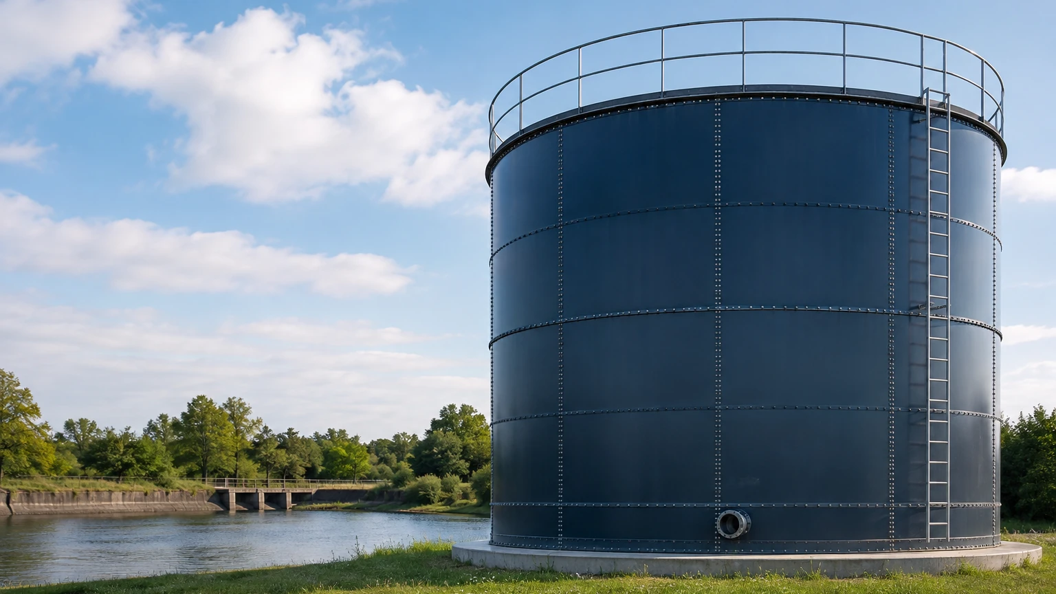
Limitations and Common Risks
While modern sensors are robust, they are not universal solutions. Engineers should be aware of the following limitations:
* Foam Interference: Heavy, thick foam (common in some wastewater or industrial processes) can absorb ultrasonic signals, leading to a "lost echo" error. In these cases, radar or hydrostatic sensors are preferred.
* Vacuum and Pressure: Ultrasonic sensors rely on air as a medium. If a tank is pressurized or under vacuum, the speed of sound changes drastically, rendering ultrasonic measurement inaccurate. Radar or hydrostatic sensors are required for pressurized vessels.
* Build-up and Scaling: In hard water applications, calcium carbonate or other minerals can build up on contact probes or the faces of ultrasonic transducers. Regular inspection and cleaning schedules must be established to maintain accuracy.
* Dielectric Constant: For non-contact radar, the ability to reflect a signal depends on the dielectric constant ($ε_r$) of the liquid. While water has a high dielectric constant ($ε_r ≈ 80$), making it an excellent reflector, some treated water or oil-water mixtures may have lower values requiring specific radar configurations.
Frequently Asked Questions (FAQ)
Q: How often should a water level sensor for water tank applications be calibrated?
A: For standard industrial water tanks, an annual calibration check is recommended. However, in critical applications like chemical dosing or high-precision process water, semi-annual checks may be necessary. Hydrostatic sensors may drift slightly over time due to diaphragm fatigue and should be zeroed periodically.
Q: Can one sensor be used for different tank shapes?
A: Yes, provided the controller or PLC is programmed with the tank's strapping table (volume-to-height mapping). The sensor measures height (m or cm); the conversion to volume (Liters or Gallons) happens in the control system.
Q: What is the maximum depth a hydrostatic sensor can measure?
A: Welk hydrostatic transmitters are capable of measuring depths up to 200 meters (approx. 656 feet) or more, depending on the pressure rating of the sensor housing and the strength of the reinforced cable.
Q: Are wireless sensors reliable for water tank monitoring?
A: Wireless sensors (using LoRaWAN or NB-IoT) are increasingly common for remote tanks where running signal cable is cost-prohibitive. They are highly reliable for monitoring, though wired sensors are still preferred for high-speed pump control loops due to latency considerations.
Conclusion
Selecting a water level sensor for water tank management involves balancing technical requirements with environmental constraints. Hydrostatic sensors offer simplicity and depth, ultrasonic sensors provide cost-effective non-contact measurement, and radar delivers the highest precision for complex environments. By following proper installation guidelines and understanding the limitations of each technology, facility managers can ensure long-term, maintenance-free operation. For detailed product selection and application engineering support, professionals are encouraged to review the available technologies on the Main Page.