What Is a Differential Pressure Transducer
What Is a Differential Pressure Transducer
In the landscape of industrial automation and process control, precision measurement is the cornerstone of safety and efficiency. Among the various instruments used to monitor fluid dynamics, the differential pressure (DP) transducer stands out as one of the most versatile and essential tools. Whether it is used to determine the level of a pressurized chemical tank, the flow rate of steam through a pipe, or the cleanliness of a filtration system, understanding the fundamental mechanics and applications of this technology is critical for modern engineering.
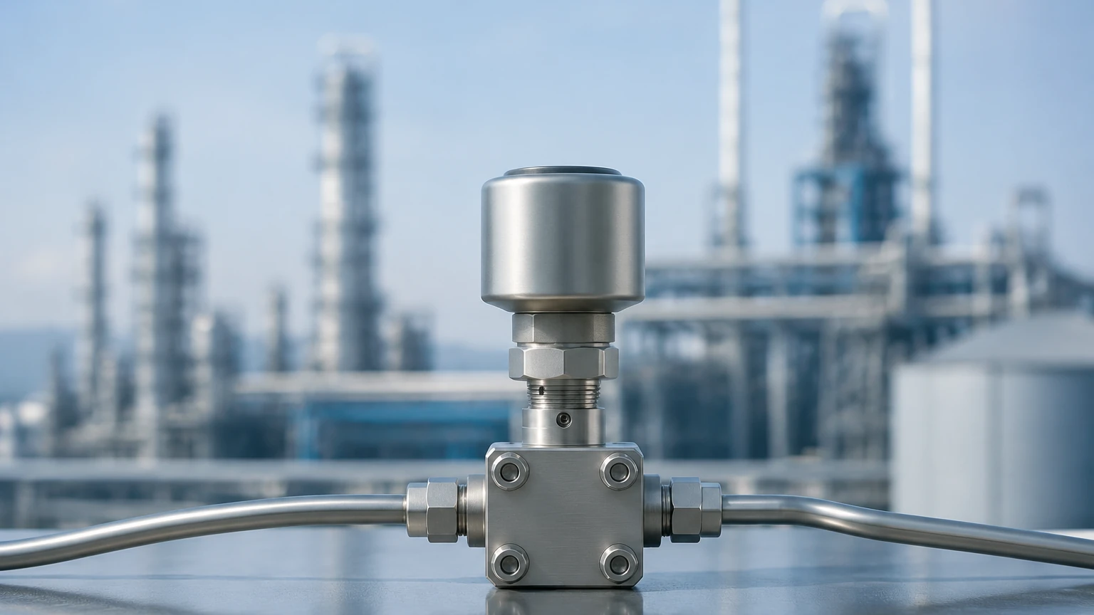
At its core, answering the question of what is a differential pressure transducer requires looking beyond a simple pressure gauge. Unlike standard pressure sensors that measure force relative to atmospheric pressure (gauge pressure) or a vacuum (absolute pressure), a differential pressure transducer measures the mathematical difference between two distinct pressure points in a system.
Understanding the Measurement Principle
The operating principle of a differential pressure transducer is based on the mechanical displacement caused by fluid force. The device typically features two sensing ports, often labeled as the "High Pressure" (HP) side and the "Low Pressure" (LP) side.
Inside the unit, a sensing element—most commonly a flexible diaphragm—is positioned between these two ports. When the pressure on the HP side exceeds the pressure on the LP side, the diaphragm deflects toward the low-pressure chamber. The magnitude of this deflection is directly proportional to the pressure difference (ΔP).
Modern transducers convert this physical movement into an electrical signal using various technologies:
* Piezoresistive Sensing: Strain gauges are integrated into a silicon diaphragm. As the diaphragm bends, the electrical resistance changes, which is then measured by a bridge circuit.
* Capacitive Sensing: The diaphragm acts as a movable electrode between two fixed capacitor plates. Movement changes the capacitance, providing a highly stable and sensitive measurement.
* Inductive Sensing: The displacement of a core within a magnetic field generates a signal proportional to the pressure change.
The resulting raw signal is then processed by internal electronics to provide a standardized output, such as 4-20 mA, 0-10 VDC, or digital protocols like HART or Modbus, allowing it to communicate with a Distributed Control System (DCS) or Programmable Logic Controller (PLC).
Key Components and Construction
To withstand harsh industrial environments, the construction of a differential pressure transducer must be robust. The "wetted parts"—those in direct contact with the process fluid—are of particular importance.
1. Isolation Diaphragms: These are the primary interfaces. They are often made from Stainless Steel 316L, but for corrosive applications, materials like Hastelloy C, Monel, or Tantalum are used.
2. Fill Fluid: A silicone oil or specialized inert fluid (for oxygen or chlorine service) transfers the pressure from the isolation diaphragm to the internal sensing element.
3. Housing: Usually rated IP66/67 or NEMA 4X, the housing protects the electronics from moisture, dust, and corrosive atmospheres.
4. Process Connections: These are typically threaded (e.g., 1/4" NPT or 1/2" NPT) or flanged for high-pressure or hygienic applications.
For engineers seeking specific hardware configurations, the Main Page of industrial suppliers provides detailed technical data sheets on material compatibility and housing ratings.
Industrial Applications: From Level to Flow
Understanding what is a differential pressure transducer also involves recognizing its diverse utility across different measurement types.
Hydrostatic Level Measurement
In the context of level measurement, DP transducers are used to calculate the height of a liquid in a tank. In an open tank, the LP side is vented to the atmosphere, and the HP side measures the pressure at the bottom. In a closed, pressurized vessel, the LP side is connected to the top of the tank to cancel out the overhead gas pressure. The level is calculated using the formula:
*P = ρ × g × h*
(Where P is pressure, ρ is fluid density, g is gravity, and h is height).
Flow Measurement
By installing a primary flow element—such as an orifice plate, Venturi tube, or Pitot tube—into a pipe, a localized pressure drop is created. The DP transducer measures the pressure before and after the restriction. According to Bernoulli’s principle, the square root of the differential pressure is proportional to the flow rate.
Filter Monitoring
In water treatment and HVAC systems, DP transducers monitor the "head loss" across a filter. As debris accumulates, the pressure difference between the inlet and outlet increases. This allows for automated alerts when maintenance or backwashing is required, preventing system failure.
Selecting the Right Differential Pressure Transducer
Selecting the correct instrument requires a balance between accuracy, environmental constraints, and cost. The following table provides a general guideline for evaluation criteria:
| Feature | Consideration | Recommendation |
| :— | :— | :— |
| Pressure Range | Maximum Operating Pressure (MWP) | Select a sensor with a range 20-30% higher than the maximum expected ΔP. |
| Accuracy | Total Probable Error (TPE) | For custody transfer flow, 0.075% accuracy is standard; for tank level, 0.2% is often sufficient. |
| Wetted Materials | Chemical Compatibility | Use SS316L for water; use Hastelloy or PTFE coatings for acids/chlorides. |
| Static Pressure | Line Pressure | Ensure the transducer can handle the total system pressure, not just the differential. |
| Output Signal | Integration | 4-20 mA HART is the industry standard for long-distance interference resistance. |
Installation and Maintenance Best Practices
Correct installation is as important as the device selection itself. Improper mounting can lead to measurement errors that are difficult to diagnose.
Impulse Line Routing
Impulse lines (the small-diameter pipes connecting the process to the transducer) must be sloped to prevent gas or liquid entrapment.
* Gas Service: The transducer should be mounted above the process line so any condensed liquid drains back into the pipe.
* Liquid Service: The transducer should be mounted below the process line so any gas bubbles rise back into the pipe.
The Role of the Manifold
A 3-valve or 5-valve manifold is a critical accessory. It allows the operator to isolate the transducer from the process, equalize the pressure between the HP and LP sides for zero-point calibration, and bleed off trapped air or fluid without shutting down the entire system.
Environmental Protection
While most industrial transducers are rugged, extreme temperature fluctuations can cause "thermal drift." In outdoor installations, sunshades or heat-traced enclosures may be necessary to maintain accuracy within the specified 0.1% to 0.5% margin.
Limitations and Common Operational Risks
Despite their versatility, differential pressure transducers have specific limitations that engineers must account for:
1. Static Pressure Limits: Every DP transducer has a maximum static pressure rating. If the system pressure exceeds this (even if the differential remains small), the internal membranes can be permanently deformed.
2. Density Variations: Since level measurement relies on fluid density, any change in temperature or concentration that alters the density will result in an incorrect level reading unless compensated for by the control system.
3. Diaphragm Plugging: In slurries or high-viscosity fluids, the small ports or impulse lines can become clogged. In these cases, a "diaphragm seal" or "remote seal" system is used to provide a larger, flush-mounted sensing surface.
4. Hydrogen Permeation: In high-pressure hydrogen applications, hydrogen atoms can diffuse through standard metal diaphragms, causing internal bubbling and sensor failure. Gold-plated diaphragms are the standard solution for this specific risk.
Frequently Asked Questions (FAQs)
Q: Can a differential pressure transducer be used for absolute pressure?
A: Yes, if the LP side is permanently evacuated and sealed under a vacuum, the device will function as an absolute pressure transducer. However, dedicated absolute sensors are usually more cost-effective for this purpose.
Q: What is the difference between a pressure transducer and a pressure transmitter?
A: Technically, a transducer converts pressure into a low-level electrical signal (like millivolts), while a transmitter amplifies and conditions that signal into a standardized output (like 4-20 mA). In modern industrial catalogs, the terms are often used interchangeably.
Q: How often should a DP transducer be calibrated?
A: Most manufacturers recommend an annual calibration check. However, in stable applications with high-quality instruments, the interval can often be extended to 2-5 years depending on the required safety integrity level (SIL).
Q: What happens if the HP and LP lines are swapped?
A: The transducer will typically show a negative or "downscale" reading (e.g., 3.8 mA in a 4-20 mA system). Many modern smart transmitters allow you to reverse the electronics via software to correct this without replumbing the lines.
Conclusion
Defining what is a differential pressure transducer reveals a device that is much more than a simple sensor; it is a fundamental component of industrial logic. By translating the subtle differences in pressure into actionable data, these instruments enable precise control over complex fluid systems. When selecting a unit, engineers must look beyond the price point and consider the long-term implications of material compatibility, static pressure limits, and installation geometry. For those in the procurement or design phase, reviewing the technical specifications on the Main Page of a dedicated manufacturer is the recommended next step to ensure the chosen technology aligns with the specific demands of the application.
Download What Is a Differential Pressure Transducer as a PDF