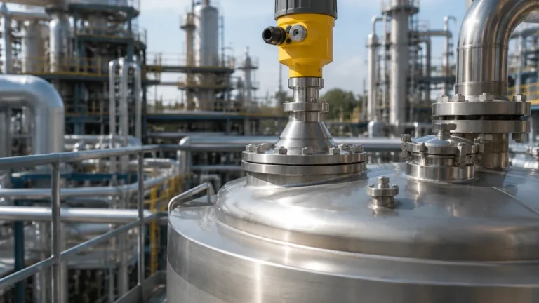
5408 Radar Level Transmitter Manual
5408 Radar Level Transmitter Manual: A Comprehensive Engineering Guide
In the landscape of modern industrial automation, non-contact level measurement has become the gold standard for accuracy and reliability. Among the various technologies available, high-frequency radar stands out for its ability to provide precise readings in the most challenging environments. This guide serves as a technical reference for engineers and procurement specialists seeking to understand the operational logic, installation requirements, and selection criteria found in a 5408 radar level transmitter manual, while highlighting the broader application of Radar Level Meters in industrial processes.
Understanding the Measurement Principle: FMCW Technology
Before diving into the specifics of device configuration, it is essential to understand the physics governing the 5408 series. Unlike older pulsed radar systems that measure the time-of-flight of a single microwave pulse, the 5408 typically utilizes Frequency Modulated Continuous Wave (FMCW) technology.
The FMCW Logic
In an FMCW system, the transmitter emits a continuous signal with a constantly changing frequency (a frequency sweep). This signal travels to the surface of the medium, reflects, and returns to the antenna. Because the transmitter is constantly changing its output frequency, there is a distinct difference between the frequency being transmitted and the frequency being received at any given moment.
This difference, known as the "beat frequency," is directly proportional to the distance the signal has traveled. By applying a Fast Fourier Transform (FFT) to the signal, the on-board electronics can distinguish between the true level reflection and background noise (such as tank agitators or internal struts) with high resolution. This allows the 5408 to maintain a high signal-to-noise ratio even in tanks with complex internal geometries.
Key Technical Specifications and Selection Criteria
When reviewing a 5408 radar level transmitter manual, the technical specifications determine the instrument's suitability for a specific process. Selecting the correct model requires an analysis of the medium's dielectric constant (εr), the process temperature, and the pressure ratings.
Selection Table: Antenna Types and Applications
| Antenna Type | Typical Beam Angle | Pressure Range | Temperature Range | Ideal Application |
| :— | :— | :— | :— | :— |
| Process Seal Antenna | 6° – 10° | Up to 160 bar | -60°C to +250°C | Corrosive liquids, hygienic applications |
| Parabolic Antenna | 3° – 4° | Up to 40 bar | -40°C to +200°C | Long-range solids, low dielectric materials |
| Cone (Horn) Antenna | 8° – 15° | Up to 100 bar | -60°C to +400°C | General purpose, large nozzles |
Dielectric Constant Considerations
The dielectric constant of the material being measured is the most critical factor in signal reflection. Materials with high dielectric constants (e.g., water-based liquids, εr > 10) reflect radar waves strongly. Non-conductive materials like oils or plastic pellets (εr < 3) allow waves to penetrate the surface, resulting in a weaker return signal. Engineers must ensure the transmitter sensitivity is adjusted according to the values specified in the manual to prevent signal loss.
Installation Best Practices for 5408 Series Transmitters
Correct physical installation is the single most important factor in ensuring the longevity and accuracy of Radar Level Meters. Most errors attributed to device failure are actually the result of improper mounting.
1. Nozzle Geometry and Placement
The transmitter should be mounted in a location where the radar beam has an unobstructed path to the product surface.
* Distance from Wall: The unit should be installed at least 200 mm (approx. 8 inches) from the tank wall to avoid interference from side-wall reflections.
* Nozzle Height: The nozzle should be as short as possible. If the nozzle is too long, the radar signal may reflect off the internal edges of the pipe before reaching the tank, creating a "dead zone" near the top of the vessel.
* Obstructions: Avoid mounting the transmitter directly above ladders, heating coils, or agitator blades. If obstructions are unavoidable, the 5408’s software often includes an "Echo Mapping" or "False Echo Suppression" feature to digitally ignore these static reflections.
2. Alignment and Leveling
For liquid applications, the antenna must be mounted perfectly perpendicular to the liquid surface. A tilt of even a few degrees can cause the signal to reflect away from the antenna rather than back toward it, especially in calm liquid conditions. In solids applications, however, a swiveling flange may be required to aim the beam at the natural angle of repose of the material.
3. Environmental Protection
While the 5408 is designed for rugged environments, using a sunshade is recommended for outdoor installations in high-temperature regions to prevent electronics overheating. Additionally, ensure the cable glands are pointed downward and properly sealed with a drip loop to prevent moisture from entering the housing via capillary action.
Configuration and Commissioning via the Device Manual
Once installed, the 5408 radar level transmitter manual provides the workflow for digital commissioning. Most modern units utilize HART, Foundation Fieldbus, or Modbus protocols for communication.
Basic Setup Steps
1. Units Selection: Define whether the output should be in metric (mm, m, m³/h) or imperial units.
2. Tank Geometry: Input the total height of the tank (Reference Point) and the "Zero" level (usually the bottom of the tank or the bottom of the discharge outlet).
3. Damping: Adjust the damping value (typically 0 to 60 seconds). A higher damping value smoothens the output in tanks with heavy turbulence or boiling surfaces but slows the response time to rapid level changes.
4. Upper and Lower Range Values: Map the 4mA and 20mA analog signals to the desired level points. For safety, it is standard practice to set the 20mA point slightly below the absolute maximum capacity of the tank to provide a buffer for overfill protection.
Application Engineering: Liquids vs. Solids
The behavior of microwaves differs significantly depending on the physical state of the medium.
Liquid Applications
In liquids, the main challenges are foam and turbulence. Heavy, dense foam can absorb the radar signal, leading to "lost echo" errors. In such cases, a lower frequency radar or a guided wave radar might be considered, though a high-sensitivity 5408 with a larger antenna can often overcome light foam layers.
Solids Applications
Solids present a different challenge: uneven surfaces and dust. Dust typically does not affect radar signals (unlike ultrasonic sensors), but the slope of a grain or powder pile can deflect the signal. The 5408 series excels here by using high-gain antennas and advanced algorithms to track the highest point of the material pile accurately.

Troubleshooting and Maintenance Protocols
Maintenance requirements for non-contact Radar Level Meters are minimal because there are no moving parts in contact with the process. However, periodic verification is necessary.
Common Error Codes and Solutions
* Signal Lost (Low Echo Strength): Often caused by heavy buildup on the antenna lens or a sudden drop in the dielectric constant of the product. Cleaning the antenna or increasing the gain settings in the manual usually resolves this.
* Fixed Output (Frozen Reading): This usually indicates that the transmitter is locked onto a false echo from an internal tank structure. Re-running the "False Echo Map" will allow the device to ignore the obstruction.
* Temperature Out of Range: The internal electronics have exceeded their rated limit. This requires improved insulation for the vessel or the addition of a cooling extension/neck for the transmitter.
Technical Comparison Table
| Feature | 5408 Standard | 5408 SIS (Safety Instrumented Systems) |
| :— | :— | :— |
| Accuracy | ± 2 mm | ± 2 mm |
| Measurement Range | Up to 40 m | Up to 40 m |
| Safety Integrity Level | N/A | SIL 2 / SIL 3 Capable |
| Diagnostics | Standard | Advanced (Smart Meter Verification) |
| Communication | HART 7, Modbus | HART 7 |
Frequently Asked Questions (FAQ)
Q: Can the 5408 radar level transmitter measure through a plastic tank roof?
A: Yes, because plastic has a low dielectric constant, the microwaves can penetrate the roof. This allows for "non-invasive" measurement where the transmitter is mounted outside the tank, though some signal strength will be lost.
Q: How does the 5408 handle vacuum conditions?
A: Radar signals do not require a medium for travel (unlike sound waves), so they perform perfectly in a vacuum. The only constraint is the pressure rating of the process seal and flange.
Q: Is periodic recalibration required?
A: Unlike hydrostatic pressure transmitters, radar sensors do not suffer from "drift." Recalibration is usually not required unless mandated by local regulatory standards or if the physical mounting position has changed.
Q: What is the "Dead Zone" or "Upper Blocking Distance"?
A: This is the area immediately below the antenna where the device cannot accurately measure. It is typically between 0 and 500 mm depending on the antenna type. The 5408 radar level transmitter manual will specify this distance, and the tank should never be filled into this zone.
Conclusion
Selecting and maintaining a 5408 radar level transmitter requires a balance of theoretical knowledge and practical application. By following the guidelines for antenna selection, adhering to strict installation geometries, and utilizing the diagnostic tools provided in the device software, engineers can achieve highly reliable level monitoring. For those seeking versatile and cost-effective solutions, Welk offers a range of professional Radar Level Meters designed to meet the rigorous demands of the global industrial sector, providing accuracy and safety across water treatment, chemical, and oil and gas applications.