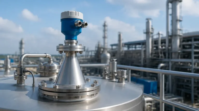
Guided Wave Radar Level Transmitter Vega
Guided Wave Radar Level Transmitter: Engineering Principles and Selection Guide
In the landscape of industrial process control, achieving precise and repeatable level measurement is fundamental to operational safety and efficiency. Among the various technologies available, the guided wave radar (GWR) transmitter stands out for its ability to handle complex media and challenging tank geometries. This guide explores the technical foundations of GWR technology, specifically focusing on the engineering considerations surrounding the guided wave radar level transmitter vega series and similar high-performance Radar Level Meters, providing a comprehensive reference for instrument engineers and procurement specialists.
Understanding the Measurement Principle: Time Domain Reflectometry (TDR)
Guided wave radar operates on the principle of Time Domain Reflectometry (TDR). Unlike non-contact radar, which emits electromagnetic pulses through the air, a GWR transmitter guides these pulses along a physical probe—typically a metal rod, cable, or coaxial tube.
The process begins when the electronics of the transmitter generate a low-energy microwave pulse. This pulse travels down the probe at the speed of light. When the pulse encounters a medium with a different dielectric constant ($ε_r$) than the one it is currently traveling through (usually air or vapor), a portion of the pulse energy is reflected back toward the transmitter.
The instrument measures the time-of-flight between the emission of the pulse and the reception of the reflection. Since the speed of the pulse is constant, the distance to the product surface is calculated using the formula:
Distance = (Speed of Light × Time Delay) / 2
The intensity of the reflection depends heavily on the dielectric constant of the medium. Materials with high dielectric constants, such as water (ε_r ≈ 80), produce very strong reflections, while hydrocarbons and solvents with low dielectric constants (ε_r < 2.0) produce much weaker signals.
Guided Wave vs. Non-Contact Radar: When to Choose GWR
While both technologies utilize microwaves, the physical guiding of the signal in GWR offers distinct advantages in specific B2B industrial environments.
Advantages of Guided Wave Radar
1. Immunity to Surface Conditions: Because the signal is focused along a probe, GWR is significantly less affected by foam, dust, or heavy vapor than non-contact radar. It is often the preferred choice for boiling liquids or agitated surfaces.
2. Narrow Beam Path: The "beam" of a GWR is confined to the immediate vicinity of the probe. This allows for installation in narrow nozzles or tanks with internal obstructions (like agitators or baffles) that would otherwise cause interference for non-contact sensors.
3. Lower Dielectric Capability: Through the use of coaxial probes, GWR can measure materials with extremely low dielectric constants that might be "invisible" to standard non-contact radar.
4. Direct Interface Measurement: GWR is uniquely capable of measuring the interface between two liquids (e.g., oil and water) because the microwave pulse can pass through the top layer and reflect off the lower layer.
Key Components of a Guided Wave Radar Level Transmitter
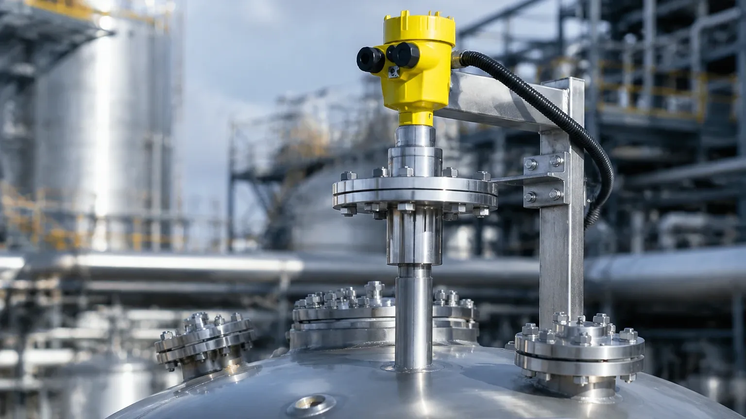
A typical industrial GWR setup, such as those found in the guided wave radar level transmitter vega product line or Welk's high-precision series, consists of three primary elements:
* The Transmitter Head: Contains the microwave generator, the receiver, and the processing electronics. Modern units often feature modular designs allowing for the replacement of electronics without opening the process vessel.
* The Process Connection: The mechanical interface (flange or thread) that mounts the instrument to the tank. It must withstand the process temperature and pressure.
* The Probe (Waveguide): The physical element in contact with the medium. Probes are selected based on the tank height and the chemical properties of the fluid.
Selection Criteria for Industrial Applications
Selecting the correct probe type is the most critical decision in GWR specification. The choice is dictated by the medium, the tank height, and the presence of internal obstacles.
1. Probe Geometry
* Single Rod Probes: Best for liquids and clean applications. They are easy to clean and resistant to buildup. Maximum lengths typically reach 6 meters (19.7 ft).
* Cable Probes: Used for tall vessels or solids. In large silos, the tensile forces exerted by falling solids can be immense; cable probes are designed to withstand these loads. Lengths can extend up to 60 meters (197 ft) or more.
* Coaxial Probes: These consist of a rod inside a tube. They provide the highest signal-to-noise ratio and are ideal for low-dielectric liquids. However, they are prone to clogging if the medium is viscous or contains solids.
2. Material Compatibility
Standard probes are usually 316L stainless steel. For corrosive environments involving acids or chlorides, materials like Hastelloy C, Monel, or PTFE coatings are required to ensure long-term reliability.
3. Process Conditions
Engineers must confirm the maximum operating temperature and pressure. High-end transmitters can handle temperatures from -196°C to +450°C and pressures up to 400 bar (5,800 psi).
Installation Guidelines and Best Practices
To ensure the accuracy of Radar Level Meters, several installation constraints must be respected:
* Nozzle Dimensions: The nozzle diameter and height can affect the signal near the top of the tank. For rod or cable probes, the nozzle should be as short and wide as possible to prevent parasitic reflections.
* Obstruction Clearance: While GWR is more forgiving than non-contact radar, the probe should still be mounted at least 300 mm (12 in) away from the tank wall or any metallic internal structures to avoid signal interference.
* Dead Zones (Blocking Distances): Every GWR has an upper and lower dead zone where measurement is either impossible or inaccurate. These are typically 50 mm to 200 mm depending on the probe type and dielectric constant.
* Centering: In deep tanks or bypass chambers, centering disks are used to keep the probe from touching the walls, which would cause a false "high level" signal.
Limitations and Application Risks
Despite its versatility, GWR is not a universal solution. Engineers should be aware of the following risks:
1. Heavy Build-up: While GWR handles some coating, extremely thick or conductive build-up (like moist coal dust or sticky resins) can bridge the gap between the probe and the tank wall, leading to signal loss.
2. Mechanical Stress: In high-flow applications or tanks with heavy agitation, the lateral force on a long rod probe can cause it to bend or break. In these cases, cable probes with weights or bypass pipes are recommended.
3. Low Dielectric Solids: If a solid material has a very low dielectric constant, the reflection may be too weak to detect reliably, especially if the material surface is slanted (angle of repose).
Technical Selection Table
| Feature | Single Rod | Single Cable | Coaxial Probe |
| :— | :— | :— | :— |
| Max Range | 6m (20 ft) | 60m+ (197 ft+) | 6m (20 ft) |
| Viscous Media | Excellent | Good | Poor (Clogging Risk) |
| Low Dielectric (ε_r < 1.6) | Poor | Poor | Excellent |
| Foam Resistance | High | High | Very High |
| Bypass Chamber Use | Recommended | Possible | Not Required |
Frequently Asked Questions (FAQ)
Q: Can a guided wave radar level transmitter vega be used for solids?
A: Yes, GWR is highly effective for solids like plastic pellets, grain, or cement. Cable probes are typically used to handle the mechanical stresses of the material movement.
Q: Does the tank material affect GWR performance?
A: Generally, no. GWR works in both metallic and non-metallic (plastic/fiberglass) tanks. However, in non-metallic tanks, the signal might be weaker unless a coaxial probe or a large mounting flange is used to provide a reference ground.
Q: How do I handle interface measurement?
A: For interface measurement, the upper liquid must have a lower dielectric constant than the lower liquid (e.g., oil over water). The upper layer must also be non-conductive. The transmitter calculates the level of both the top surface and the interface layer simultaneously.
Q: Is calibration required on-site?
A: Most modern GWR units come pre-calibrated. On-site commissioning usually involves entering the tank height, probe length, and the dielectric range of the medium via a local display or HART/Fieldbus communication.
Conclusion
The implementation of a guided wave radar level transmitter vega or a comparable industrial GWR solution offers a robust answer to the complexities of modern process measurement. By guiding the microwave signal directly to the target, these instruments bypass many of the environmental challenges that hinder other technologies. When specified with the correct probe geometry and material, GWR provides the reliability required for safety-critical and high-accuracy industrial applications. For further technical specifications and product comparisons, reviewing specialized Radar Level Meters documentation is recommended to ensure the selected hardware aligns with the specific chemical and mechanical demands of the facility.