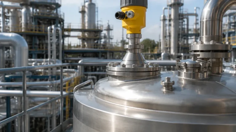
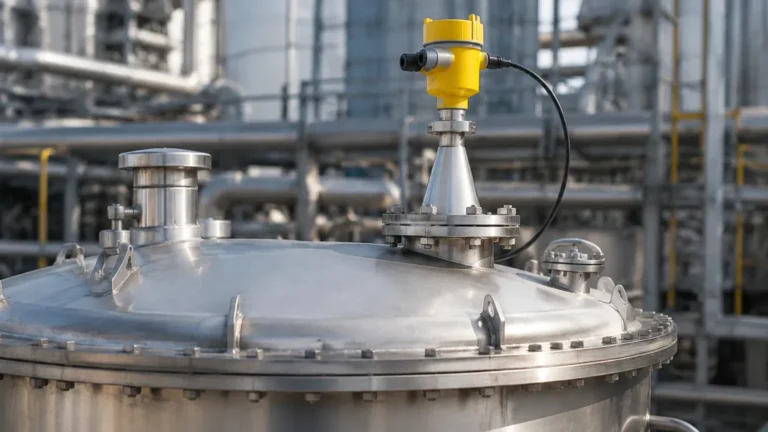
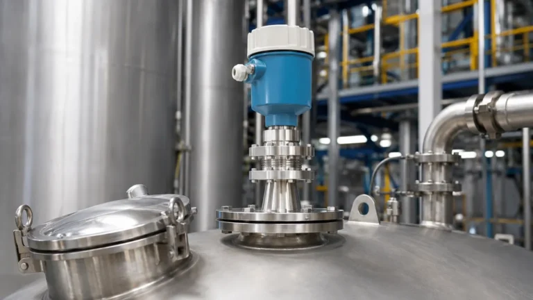
Radar Level Measurement Endress Hauser
Radar Level Measurement: An Engineering Guide to Technology and Industry Standards
In the landscape of industrial automation, precise level measurement is a cornerstone of process safety, inventory management, and operational efficiency. Among the various technologies available, radar-based systems have emerged as the gold standard for challenging environments. This guide explores the technical foundations of radar level measurement, with a particular focus on the engineering standards established by industry leaders and the practical considerations for selecting Radar Level Meters for modern industrial applications.
Understanding Radar Measurement Principles
Radar level measurement operates on the principle of Time-of-Flight (ToF). The instrument emits electromagnetic pulses or continuous wave signals that travel at the speed of light. When these signals encounter a medium with a different dielectric constant ($ε_r$) than the surrounding air or gas, a portion of the energy is reflected back to the sensor. By measuring the time interval between emission and reception, the device calculates the distance to the product surface.
There are two primary methodologies used in modern radar instrumentation:
1. Pulse Radar (PTOF)
Pulse radar, or Pulsed Time-of-Flight, sends short microwave pulses toward the material surface. The sensor remains in a "receive" mode between pulses to capture the reflected signal. This technology is known for its low power consumption and is often used in battery-powered or loop-powered transmitters. However, it may struggle with low-reflectivity surfaces or high-turbulence environments where signal clarity is compromised.
2. Frequency Modulated Continuous Wave (FMCW)
FMCW radar transmits a continuous signal with a constantly changing frequency (a frequency sweep). The reflection from the product surface is received and compared to the signal being transmitted at that exact moment. The frequency difference between the transmitted and received signals is directly proportional to the distance. FMCW is generally more accurate and provides better signal-to-noise ratios, making it the preferred choice for high-precision custody transfer and complex process vessels.
Comparing Free-Space and Guided Wave Radar
When evaluating radar technology, engineers must choose between non-contact (free-space) and contact (guided wave) configurations.
Free-Space Radar
Free-space radar level meters transmit signals through the air via an antenna (horn, teardrop, or planar). Because they do not touch the process media, they are ideal for corrosive, viscous, or abrasive materials. They are also suitable for applications where mechanical agitators or internal vessel structures would interfere with a physical probe.
Guided Wave Radar (GWR)
Guided Wave Radar utilizes a physical probe (rod, cable, or coaxial) to direct the microwave signal to the surface. This "guided" approach significantly reduces signal loss and dispersion. GWR is exceptionally effective for liquids with low dielectric constants, such as liquefied gases or hydrocarbons, and is largely unaffected by foam, steam, or dust. It is also the primary choice for interface measurement (e.g., the boundary between oil and water).
The Role of Frequency in Radar Performance
The frequency at which a radar meter operates dictates its beam angle and sensitivity. Common industrial frequencies include:
* 6 GHz (C-Band): Known for its ability to penetrate heavy foam and steam. It has a wider beam angle, which requires larger nozzles and clear paths within the tank.
* 26 GHz (K-Band): The long-standing industry standard for general-purpose liquid and solid measurement. It balances antenna size with signal focus.
* 80 GHz (W-Band): The modern benchmark for high-precision measurement. The high frequency allows for extremely narrow beam angles (as small as 3°), enabling the sensor to avoid internal obstructions like heating coils or agitators. It also allows for smaller process connections, often as small as 20 mm (3/4").
Industry Benchmark: Radar Level Measurement Endress Hauser
When discussing high-performance instrumentation, the standards set by radar level measurement endress hauser systems are often used as a reference point for reliability and innovation. Their Micropilot (free-space) and Levelflex (guided wave) series have introduced several critical concepts to the B2B market:
1. Multi-Echo Tracking: Advanced algorithms that can distinguish between the true level signal and interference reflections from tank walls or agitators.
2. Heartbeat Technology: A diagnostic suite that allows for continuous self-monitoring and verification of the instrument's health without interrupting the process. This is vital for safety-instrumented systems (SIS) and meeting SIL2/SIL3 requirements.
3. HistoROM Data Management: Integrated memory modules that store configuration and event logs, simplifying device replacement and commissioning.
Engineers often look to these features when specifying equipment for critical infrastructure, as they minimize the total cost of ownership through reduced maintenance and simplified calibration.
Selection Criteria and Selection Table
Selecting the correct radar instrument requires a detailed analysis of the process environment. The following table provides a general framework for technology selection based on common industrial parameters.
| Parameter | Free-Space (80 GHz) | Free-Space (26 GHz) | Guided Wave Radar (GWR) |
| :— | :— | :— | :— |
| Accuracy | ±1 mm to ±2 mm | ±2 mm to ±5 mm | ±2 mm |
| Dielectric Constant (ε_r) | Low to High (≥ 1.4) | Medium to High (≥ 1.9) | Very Low (≥ 1.2) |
| Heavy Foam | Moderate | Moderate | Excellent |
| Turbulent Surface | Good | Moderate | Excellent |
| Internal Obstructions | Excellent (Narrow Beam) | Moderate | Excellent (Guided) |
| Maximum Range | Up to 125 m | Up to 70 m | Up to 75 m |
| Maintenance | Lowest (Non-contact) | Lowest (Non-contact) | Low (Contact) |
Installation Best Practices
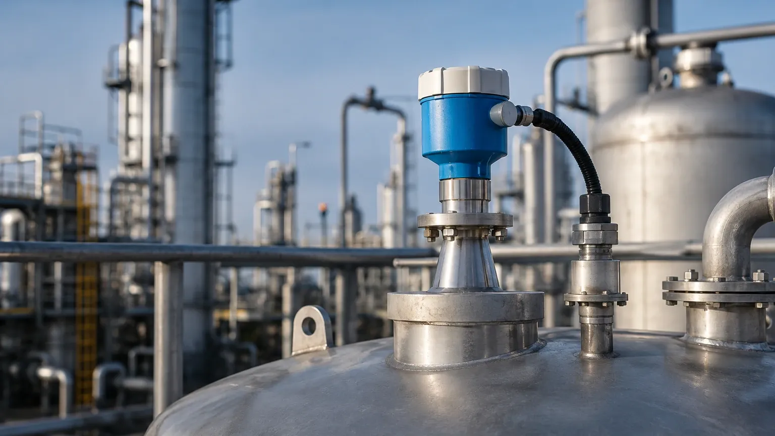
Even the most advanced radar level meter will fail if installed incorrectly. Engineers must adhere to the following constraints:
* Nozzle Geometry: The nozzle height should be kept to a minimum to prevent signal interference from the nozzle walls. For 80 GHz units, the nozzle can be longer, but for 26 GHz units, the antenna should ideally extend slightly beyond the nozzle end.
* Blocking Distance (Dead Zone): Every radar sensor has a minimum distance (typically 50 mm to 300 mm) from the antenna where measurement is not possible. Ensure the maximum fill level does not enter this zone.
* Mounting Position: Sensors should generally be mounted at 1/6th of the tank diameter from the wall. Mounting too close to the wall causes interference, while mounting in the center can lead to multiple reflections in domed-roof tanks.
* Avoid the Inflow: Never install the sensor directly above the filling stream, as the turbulence and material flow will create significant noise and false readings.
Limitations and Application Risks
While radar is versatile, it is not a universal solution. Engineers must account for:
1. Extremely Low Dielectric Media: Materials like liquefied hydrogen or certain dry powders may not reflect enough energy. In these cases, GWR with a coaxial probe or a specialized high-sensitivity free-space radar is required.
2. Heavy Dust and Build-up: In solid applications, significant dust can attenuate the signal. 80 GHz radar handles dust better than lower frequencies, but air purging systems may still be necessary to keep the antenna lens clean.
3. Vessel Geometry: Spherical tanks or tanks with conical bottoms can cause signal focusing or scattering. Advanced software mapping (False Echo Suppression) is required to "teach" the device to ignore these static reflections.
Frequently Asked Questions (FAQ)
Q: Can radar measure the level through a plastic tank wall?
A: Yes, free-space radar can often measure through non-conductive materials like plastic (HDPE, PP) or glass, allowing for non-invasive measurement of chemicals in IBCs or storage tanks.
Q: How does temperature and pressure affect radar accuracy?
A: Unlike ultrasonic sensors, radar signals are electromagnetic and are not significantly affected by air temperature, pressure, or vacuum. However, extreme temperatures may require specialized cooling fins or high-temperature seal materials for the sensor electronics.
Q: Is 80 GHz always better than 26 GHz?
A: Not necessarily. While 80 GHz offers a narrower beam and better accuracy, 26 GHz is often more cost-effective for simple water/wastewater applications and is less sensitive to condensation build-up on the antenna.
Conclusion
Radar level measurement represents the pinnacle of industrial level sensing, offering a robust, non-contact solution for a wide array of media. By understanding the nuances of frequency, signal processing, and installation constraints, engineering teams can implement systems that provide years of maintenance-free service. Whether utilizing the advanced diagnostic capabilities found in radar level measurement endress hauser benchmarks or deploying standard 26 GHz transmitters for utility tanks, the key to success lies in matching the technology to the specific dielectric and physical properties of the process environment. For those looking to upgrade their current systems, reviewing the latest Radar Level Meters provides a path toward improved process transparency and safety.