Magnetic Flow Meter Principle
Magnetic Flow Meter Principle
In the realm of industrial process control, the magnetic flow meter, often referred to as a magmeter, stands as one of the most versatile and reliable instruments for measuring the flow of conductive liquids. Unlike mechanical flow meters that rely on moving parts like turbines or gears, magnetic flow meters utilize electromagnetic properties to determine flow velocity. This article provides a comprehensive technical overview of the magnetic flow meter principle, its mechanical construction, selection criteria, and the practical considerations necessary for successful deployment in industrial environments.
Understanding Faraday’s Law of Electromagnetic Induction
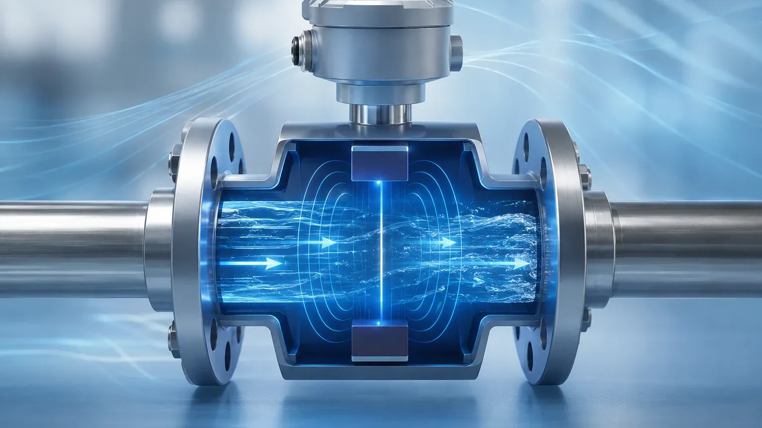
The fundamental magnetic flow meter principle is based on Faraday’s Law of Electromagnetic Induction, first formulated by Michael Faraday in 1831. The law states that a voltage is induced when a conductor moves through a magnetic field. In the context of a flow meter, the "conductor" is the process fluid itself, provided it possesses a minimum level of electrical conductivity.
The relationship is mathematically expressed by the following equation:
E = k · B · v · D
Where:
* E is the induced voltage (the signal generated by the flow).
* k is a constant specific to the instrument.
* B is the strength of the magnetic field generated by the meter’s coils.
* v is the average velocity of the conductive fluid.
* D is the inner diameter of the pipe (the distance between the electrodes).
When the conductive liquid flows through the flow tube, it passes through a magnetic field generated by a pair of electromagnetic coils located outside the flow stream. As the liquid (the conductor) moves through this field at a certain velocity (v), it generates a voltage (E) that is directly proportional to the flow speed. This voltage is picked up by two electrodes mounted on opposite sides of the pipe wall. Because the magnetic field strength (B) and the pipe diameter (D) are constant, the induced voltage is a linear function of the fluid velocity. The transmitter then converts this micro-voltage signal into a standard industrial output, such as 4-20mA or a digital pulse.
Key Components and Construction
To apply the magnetic flow meter principle effectively, the instrument is constructed with specific components designed to maintain the integrity of the magnetic field and the sensitivity of the voltage detection.
1. The Flow Tube
The flow tube is typically constructed from non-magnetic stainless steel. This prevents the tube itself from interfering with the magnetic field generated by the coils. The tube must be rigid enough to withstand process pressures while providing a stable housing for the internal components.
2. The Liner
Since the flow tube is usually metallic and conductive, an insulating liner is required to prevent the induced voltage from short-circuiting through the pipe wall. The liner material is chosen based on its chemical compatibility with the process fluid and its temperature resistance. Common materials include PTFE, PFA, and various types of rubber.
3. Electromagnetic Coils
These coils are positioned on the exterior of the flow tube (but inside the meter housing). When energized by the transmitter, they produce a uniform magnetic field across the cross-section of the pipe. Modern meters often use pulsed DC (direct current) excitation to minimize the effects of electrochemical noise and zero-point drift.
4. Electrodes
A pair of electrodes is installed flush with the liner. These electrodes are the only parts, along with the liner, that come into direct contact with the process fluid. They detect the induced voltage generated by the fluid movement. For specific applications involving high-solids or abrasive slurries, specialized electrode designs (such as bullet-head or replaceable electrodes) may be used.
Material Selection and Evaluation Criteria
Selecting the right materials is critical for ensuring the longevity of the device. Because the magnetic flow meter principle requires the fluid to be in contact with the electrodes and the liner, chemical compatibility is the primary concern. Engineers should consult the Main Page of technical providers to review specific chemical resistance charts before finalizing a specification.
Table 1: Common Liner Materials
| Material | Temperature Range | Typical Applications |
| :— | :— | :— |
| PTFE (Teflon) | -40°C to +180°C | Strong acids, bases, and high-temperature chemicals. |
| PFA | -40°C to +180°C | Similar to PTFE but with better vacuum resistance. |
| Neoprene | 0°C to +60°C | Water treatment, wastewater, and general purpose. |
| Polyurethane | -10°C to +60°C | Highly abrasive slurries, mining, and sand-bearing water. |
| F46 (FEP) | -40°C to +150°C | Corrosive media with moderate mechanical stress. |
Table 2: Electrode Material Selection
| Electrode Material | Application Suitability |
| :— | :— |
| Stainless Steel 316L | Low-corrosion liquids, water, and organic acids. |
| Hastelloy B/C | Seawater, oxidizing salts, and various chemical processing. |
| Titanium | Chlorides, hypochlorites, and wet chlorine. |
| Tantalum | Almost all acids (except hydrofluoric) and high-corrosion environments. |
| Platinum-Iridium | Extreme chemical resistance, though high cost. |
Installation Guidelines for Optimal Accuracy
While the magnetic flow meter principle is robust, the accuracy of the measurement is highly dependent on proper installation. Most industrial magmeters offer an accuracy of ±0.5% of the flow rate, but this can degrade if the flow profile is disturbed.
Straight Pipe Requirements
To ensure a stable and symmetrical flow profile, the meter requires a minimum length of straight pipe both upstream and downstream of the installation point.
* Upstream: Typically 5 times the nominal diameter (5D).
* Downstream: Typically 2 times the nominal diameter (2D).
If there are heavy disturbances like valves or pumps immediately before the meter, these requirements may increase to 10D or more.
Fluid Conductivity
The fluid must meet a minimum conductivity threshold, usually 5 μS/cm (microsiemens per centimeter). Deionized water or pure hydrocarbons (like oil or gasoline) cannot be measured using the magnetic flow meter principle because they do not have enough free ions to generate a measurable voltage.
Full Pipe Condition
The meter must be installed in a location where the pipe is always completely full of liquid. If the pipe is partially empty, the meter will calculate the flow based on the full cross-sectional area, leading to significant overestimation of the flow rate. For this reason, vertical installations with upward flow are often preferred.
Grounding
Grounding is perhaps the most overlooked aspect of magmeter installation. Since the induced voltage is often in the millivolt range, any stray electrical currents in the piping system can interfere with the signal. The fluid, the flow tube, and the transmitter must all be at the same electrical potential. This is achieved using grounding rings or grounding electrodes, especially when the meter is installed in plastic or lined piping.
Common Limitations and Application Risks
Despite their advantages, magnetic flow meters are not universal solutions. Understanding their limitations is essential for process engineers.
1. Conductivity Requirements: As mentioned, non-conductive fluids like oils, alcohols, and gases cannot be measured. If the conductivity drops below the manufacturer's threshold, the signal will become unstable and eventually fail.
2. Electrode Coating: In applications involving fats, oils, or certain minerals, a film can build up on the electrodes. This coating acts as an insulator, preventing the electrodes from sensing the induced voltage. Regular maintenance or the use of ultrasonic electrode cleaning features may be necessary.
3. Vacuum Conditions: Some liners, particularly PTFE, can collapse or pull away from the tube wall if the system experiences a vacuum. If vacuum conditions are possible, PFA liners with mechanical reinforcement (like a metal mesh) should be specified.
4. Air Bubbles: Large air bubbles or entrained gas in the liquid can cause signal noise and inaccuracies. The meter cannot distinguish between the volume of the liquid and the volume of the gas bubbles.
Maintenance and Troubleshooting
One of the primary benefits of the magnetic flow meter principle is the lack of maintenance required due to the absence of moving parts. However, troubleshooting is occasionally necessary if the readings become erratic.
* Zero-Point Check: If the meter shows a flow reading when the pumps are off and the valves are closed, the pipe may not be full, or there may be a grounding issue.
* Insulation Resistance: If the liner is damaged and fluid reaches the coils, the insulation resistance will drop, causing the meter to fail. This can be tested using a megohmmeter during a shutdown.
* Signal Noise: High-frequency noise is often caused by chemical reactions at the electrode surface or by the presence of large solids hitting the electrodes. Adjusting the excitation frequency or increasing the damping (filtering) in the transmitter settings can often mitigate this.
Frequently Asked Questions (FAQs)
Q: Can magnetic flow meters measure steam or compressed air?
A: No. The magnetic flow meter principle requires a conductive liquid. Gases and steam do not have the necessary conductivity to generate an induced voltage.
Q: What is the minimum flow velocity required?
A: Most magmeters can measure velocities as low as 0.1 m/s to 0.3 m/s, but for optimal accuracy, it is recommended to size the meter so that the normal operating flow is between 2 m/s and 4 m/s.
Q: Does the viscosity of the fluid affect the measurement?
A: Generally, no. As long as the flow is turbulent and the pipe is full, viscosity does not affect the induced voltage. However, extremely high viscosity may affect the flow profile and require longer straight pipe runs.
Q: How long do these meters typically last?
A: In non-corrosive water applications, magnetic flow meters can last 20 years or more. In highly corrosive or abrasive applications, the lifespan depends entirely on the correct selection of liner and electrode materials.
Conclusion
The magnetic flow meter principle offers a highly accurate, obstruction-free method for measuring the flow of conductive liquids across a wide range of industries, from municipal water treatment to aggressive chemical processing. By understanding Faraday’s Law and the importance of material compatibility and proper installation, engineers can ensure reliable long-term performance. For those seeking specific instrumentation for industrial automation, it is advisable to Review product options and application support to find the most cost-effective and technically sound solution for their specific process requirements.