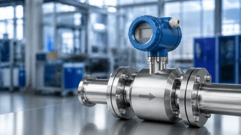
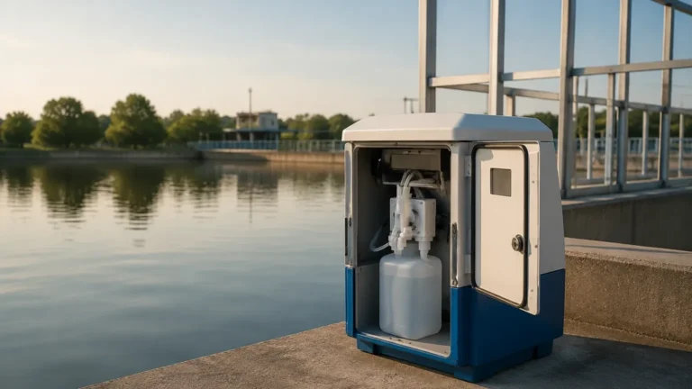
Process Conductivity Cell
Process Conductivity Cell
In the landscape of industrial process control, the measurement of liquid properties is essential for maintaining product quality, ensuring equipment longevity, and optimizing chemical dosing. Among the most critical parameters is electrolytic conductivity. A process conductivity cell is the primary sensing element used to measure the ability of a solution to conduct an electrical current. This measurement serves as a proxy for the concentration of dissolved ions, making it indispensable in water treatment, chemical processing, and pharmaceutical manufacturing.
Understanding the technical nuances of a process conductivity cell is vital for engineers and plant managers who must select the right instrumentation for challenging environments. Whether monitoring the purity of deionized water or the concentration of caustic cleaning solutions, the choice of sensor technology directly impacts the reliability of the control loop.
Understanding the Measurement Principle
Before selecting a process conductivity cell, it is important to understand the physics behind the measurement. Conductivity is the reciprocal of resistivity. In a liquid, current is carried by ions. Therefore, as the concentration of dissolved salts, acids, or bases increases, the conductivity of the solution typically rises.
The Cell Constant (K)
A process conductivity cell consists of two or more electrodes of a specific surface area (A) separated by a fixed distance (L). The ratio of the distance to the area is known as the cell constant ($K = L/A$).
* Low Cell Constants (e.g., K=0.01 to 0.1 cm⁻¹): These are used for high-purity water applications. The electrodes are placed close together or have a large surface area to detect the very small number of ions present.
* High Cell Constants (e.g., K=1.0 to 10.0 cm⁻¹): These are used for concentrated chemicals or wastewater. The electrodes are spaced further apart to prevent the current from becoming too high for the transmitter to process.
Contacting vs. Inductive Measurement
There are two primary methods used by a process conductivity cell to interact with the fluid:
1. Contacting Conductivity: This method uses metal or graphite electrodes that come into direct contact with the process fluid. An AC voltage is applied between the electrodes, and the resulting current is measured. While highly accurate for low-conductivity fluids, these cells are susceptible to fouling, polarization, and corrosion.
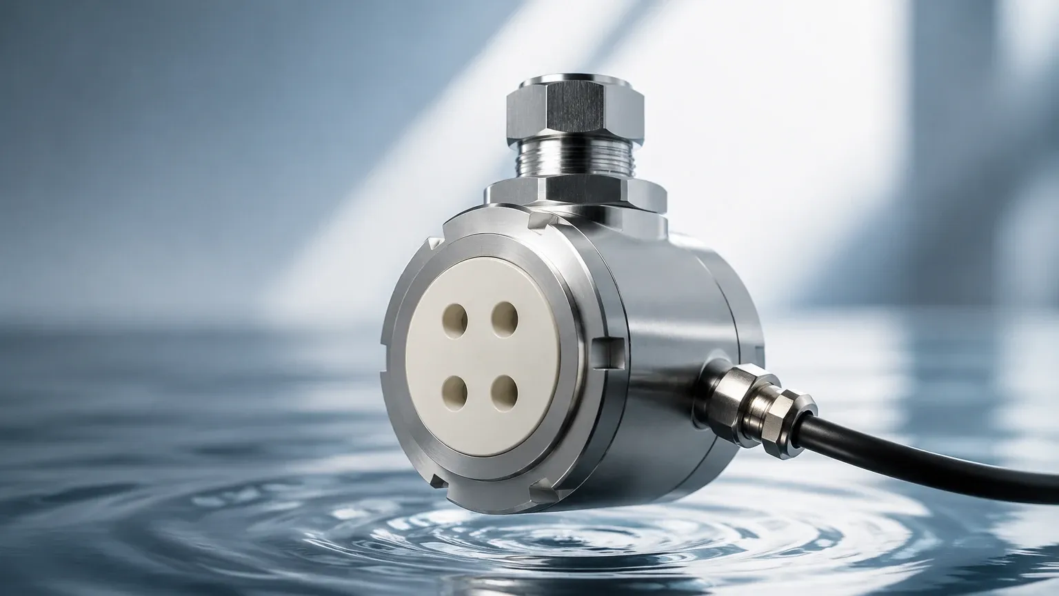
2. Inductive (Toroidal) Conductivity: This method uses two wire-wound metal toroids encased in a plastic or ceramic housing. One coil induces an electric current in the conductive liquid, and the second coil detects the magnitude of that current. Because the sensor does not have exposed electrodes, it is ideal for highly corrosive, oily, or fouling-prone liquids.
Types of Process Conductivity Cells
Selecting the appropriate cell type depends on the expected conductivity range and the chemical nature of the process fluid.
2-Electrode Cells
Most commonly used in pure and ultrapure water applications. They are simple and cost-effective but can suffer from "polarization error" at higher conductivity levels, where a layer of ions builds up at the electrode surface, creating an artificial resistance.
4-Electrode Cells
These utilize two drive electrodes and two sensing electrodes. By measuring the voltage drop across the sensing electrodes, the system can compensate for fouling and polarization. This makes the 4-electrode process conductivity cell suitable for a wide range of industrial applications, from wastewater to chemical concentration monitoring.
Inductive (Electrodeless) Sensors
As mentioned, these are the "workhorses" for aggressive environments. They are frequently used in cooling towers, brine concentration, and acid/base dilution systems. They require virtually no maintenance compared to contacting sensors in dirty applications.
Key Evaluation Criteria for Industrial Applications
When evaluating a process conductivity cell for a specific project, consider the following technical factors:
1. Measurement Range
Determine the minimum and maximum expected conductivity. For ultrapure water (0.055 µS/cm), a contacting cell with a low cell constant is mandatory. For seawater (approx. 50 mS/cm) or concentrated acids, an inductive sensor is preferred.
2. Material Compatibility
The wetted materials must withstand the process temperature, pressure, and chemical composition. Common materials include:
* 316L Stainless Steel: Standard for water and non-corrosive chemicals.
* Titanium: Excellent for salt water and aggressive oxidizers.
* Graphite: Used in high-temperature or high-conductivity contacting cells.
* PEEK or PFA: Common coatings for inductive sensors to resist high temperatures and strong acids.
3. Temperature Compensation
Conductivity is highly temperature-dependent; typically, conductivity increases by about 2% for every 1°C rise in temperature. A high-quality process conductivity cell must include an integrated temperature sensor (such as a Pt100 or Pt1000) to allow the transmitter to provide a temperature-compensated reading (usually referenced to 25°C).
4. Pressure and Temperature Ratings
Industrial processes often operate at elevated pressures. Ensure the sensor body and its mounting hardware (threaded, flanged, or tri-clamp) are rated for the maximum possible process conditions. For instance, a cell in a boiler blowdown line may need to withstand 200°C and 20 bar (approx. 290 psi).
Practical Selection Table
| Application Type | Conductivity Range | Recommended Cell Type | Typical Cell Constant (K) |
| :— | :— | :— | :— |
| Ultrapure Water / RO | 0.01 – 20 µS/cm | 2-Electrode (Stainless) | 0.01 to 0.1 |
| Drinking Water | 50 – 1000 µS/cm | 2-Electrode or 4-Electrode | 0.1 to 1.0 |
| Wastewater / Cooling Water | 1000 – 10,000 µS/cm | 4-Electrode or Inductive | 1.0 |
| Concentrated Acids/Bases | >10,000 µS/cm | Inductive (Toroidal) | N/A (Inductive) |
| Food & Beverage (CIP) | 100 – 500 mS/cm | Inductive (Hygienic) | N/A (Inductive) |
Installation and Mounting Guidelines
Proper installation of a process conductivity cell is as important as the sensor selection itself. Incorrect placement can lead to air bubbles, stagnant flow, or electrical interference, all of which result in inaccurate data.
* Avoid Air Pockets: Sensors should be installed in a position where they are always fully submerged. In horizontal pipes, mount the sensor from the side or bottom, never from the top where air can trap.
* Flow Direction: For contacting cells, the flow should ideally enter the open end of the electrode to ensure a representative sample and to help flush away debris.
* Pipe Clearance: Inductive sensors require a minimum clearance from pipe walls (often at least 20-30 mm) to prevent the pipe material from interfering with the magnetic field. If installed in a plastic pipe, the field is unaffected, but metal pipes require careful centering.
* Cable Management: Conductivity signals, especially in low-range applications, are sensitive to electromagnetic interference (EMI). Use shielded cables and keep them away from high-voltage power lines. For a wide range of industrial instrumentation solutions including level and flow, you can explore the Main Page of our technical catalog for compatible transmitters.
Integration with Level and Process Control Systems
In many industrial setups, conductivity measurement is used in conjunction with level measurement. For example, in a chemical storage tank, a Welk level transmitter monitors the volume, while a process conductivity cell monitors the concentration or identifies the interface between two different liquids (such as oil and water).
In water treatment skids, conductivity data is fed into a PLC (Programmable Logic Controller) to trigger automated valves for boiler blowdown or to signal when an ion-exchange resin bed is exhausted and requires regeneration. The synergy between level, flow, and analytical sensors like the conductivity cell ensures a holistic view of the process state.
Maintenance, Calibration, and Troubleshooting
While modern process conductivity cells are robust, they are not "set and forget" devices.
Cleaning
Fouling is the most common cause of error. In contacting cells, oils or scales can coat the electrodes, leading to low readings. Cleaning with a mild detergent or a weak acid (depending on the contaminant) is usually sufficient. Inductive sensors are much easier to clean due to their smooth, non-metallic surfaces.
Calibration and Verification
Calibration involves checking the sensor against a standard solution of known conductivity.
1. Dry Check: Ensure the sensor reads zero in air.
2. Standard Comparison: Submerge the cleaned sensor in a fresh calibration standard. Ensure the temperature has stabilized before adjusting the transmitter.
3. Cell Constant Adjustment: Over time, the physical dimensions of the electrodes may change slightly due to corrosion or abrasion. The transmitter allows for a "Cell Constant Adjustment" to compensate for these minor shifts.
Common Risks and Limitations
* Polarization: Occurs in 2-electrode sensors at high conductivities. Switch to 4-electrode or inductive types if this is an issue.
* Cable Capacitance: In very low conductivity applications, long cable runs can introduce capacitance that affects the AC measurement. Keep cables as short as possible or use a transmitter with a pre-amplifier.
* Chemical Attack: Always verify that the sensor O-rings and body material are compatible with the process media to prevent catastrophic seal failure.
Frequently Asked Questions (FAQs)
Q: How often should I calibrate my process conductivity cell?
A: This depends on the application. In ultrapure water, once or twice a year may suffice. In wastewater or chemical processing, monthly verification is recommended until a stability trend is established.
Q: Can I use a contacting sensor for seawater?
A: While possible, the high salt content will likely cause polarization and potential corrosion. An inductive (toroidal) sensor is much better suited for the high conductivity and corrosive nature of seawater.
Q: What is the difference between conductivity and TDS?
A: Conductivity measures the ability to pass current, while TDS (Total Dissolved Solids) refers to the mass of dissolved minerals. Transmitters often use a conversion factor (typically 0.5 to 0.7) to estimate TDS from a conductivity reading.
Q: Does the flow rate affect the conductivity reading?
A: Generally, no. Conductivity is an intrinsic property of the fluid. However, a minimum flow is often required to ensure the sensor sees a representative sample of the process and to prevent the buildup of bubbles or sediment.
By carefully selecting the cell constant, electrode material, and measurement technology, engineers can ensure that their process conductivity cell provides the accurate, real-time data necessary for efficient industrial operations. For more information on integrating these sensors with broader automation and level control systems, visit the Main Page for detailed product specifications and application support.