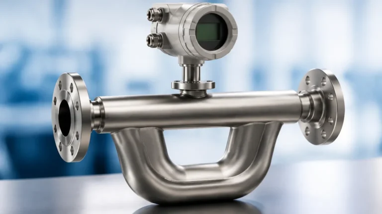
Magnetic Flow Sensor
Magnetic Flow Sensor
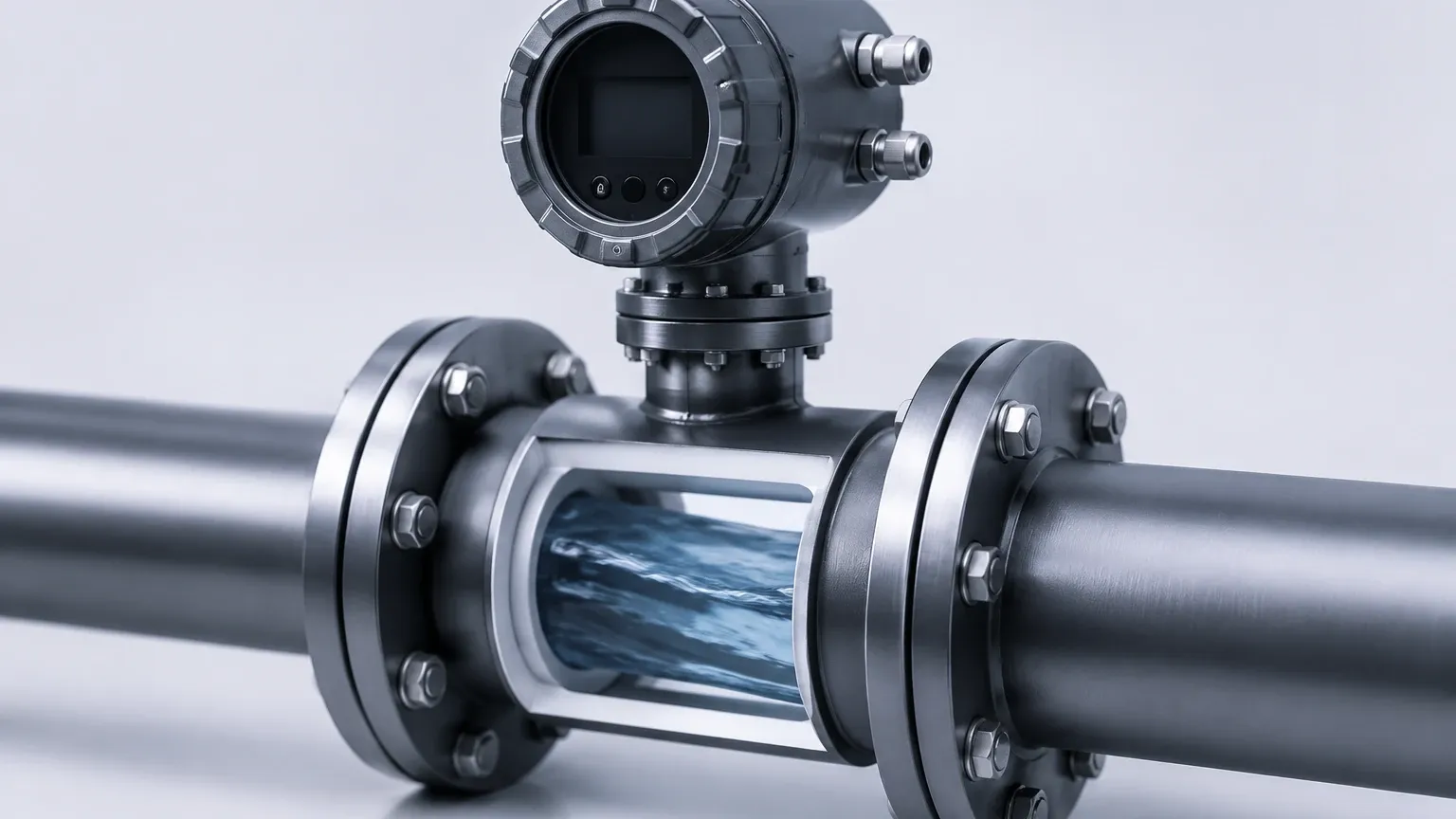
In the landscape of industrial process control, the magnetic flow sensor, often referred to as an electromagnetic flowmeter or "magmeter," stands as a cornerstone technology for measuring the flow of conductive liquids. Unlike mechanical flow meters that rely on turbines or gears, magnetic flow sensors operate on non-intrusive principles, making them ideal for challenging applications ranging from wastewater treatment to the processing of corrosive chemicals. This guide provides a technical deep dive into the engineering principles, selection criteria, and installation best practices for magnetic flow sensors in B2B industrial environments.
Fundamental Principles of Magnetic Flow Sensors
The operation of a magnetic flow sensor is governed by Faraday’s Law of Electromagnetic Induction. This law states that a voltage is induced when a conductive medium moves through a magnetic field. In the context of a flow sensor, the pipe serves as the conduit, and the liquid flowing through it acts as the conductor.
The Mathematical Foundation
The induced voltage ($E$) is directly proportional to the velocity of the liquid ($V$), the strength of the magnetic field ($B$), and the distance between the electrodes ($D$), which typically corresponds to the inner diameter of the pipe. The relationship is expressed by the formula:
$$E = k \cdot B \cdot D \cdot V$$
Where:
* $E$: Induced voltage (measured in millivolts).
* $k$: Meter constant (a calibration factor).
* $B$: Magnetic field strength generated by the coils.
* $D$: Distance between electrodes (pipe diameter).
* $V$: Mean velocity of the fluid.
As the fluid moves through the magnetic field generated by coils located outside or within the sensor body, the electrodes detect the resulting voltage. Because $B$ and $D$ are constant in a fixed installation, the induced voltage is a linear representation of the fluid velocity. This signal is then processed by a transmitter and converted into a volumetric flow rate (e.g., cubic meters per hour or liters per minute).
Component Engineering: Linings and Electrodes
Because the magnetic flow sensor must be in direct contact with the process fluid, the choice of materials for the internal lining and the electrodes is critical for long-term reliability and accuracy. For engineers integrating these sensors into broader automation systems, reviewing the Main Page of instrumentation providers can offer insights into how these sensors complement level measurement technologies in complex tank and piping layouts.
Lining Materials
The lining serves two purposes: it protects the sensor housing from corrosion and ensures the induced voltage is not shorted out by a metal pipe wall. Common materials include:
* PTFE (Teflon): Highly resistant to chemicals and high temperatures (up to 180°C / 356°F). It is the standard for aggressive acids and bases.
* PFA: Similar to PTFE but offers better mechanical stability at high temperatures and is often used in food and beverage applications due to its smooth surface.
* Hard/Soft Rubber: Primarily used in water and wastewater applications. Soft rubber is excellent for abrasive slurries (e.g., mining or pulp and paper).
* Ceramic: Used for extremely high-temperature applications or where maximum abrasion resistance is required, though it is more brittle than polymer linings.
Electrode Materials
The electrodes are the "sensing" points that pick up the induced voltage. They must be chemically compatible with the fluid to prevent pitting or scaling.
* Stainless Steel (316L): Suitable for water and mildly corrosive liquids.
* Hastelloy C: Used for more aggressive chemical environments.
* Titanium: Ideal for seawater and brine applications.
* Tantalum/Platinum: Reserved for the most extreme corrosive environments, such as concentrated sulfuric or nitric acid.
Technical Selection Criteria for Process Industries
Selecting the correct magnetic flow sensor requires a thorough understanding of the process fluid and the hydraulic conditions of the system. The following table provides a practical reference for initial evaluation.
Table 1: Magnetic Flow Sensor Selection Matrix
| Feature | Specification / Requirement | Engineering Consideration |
| :— | :— | :— |
| Minimum Conductivity | > 5 μS/cm (standard) | Not suitable for oil, deionized water, or hydrocarbons. |
| Fluid State | Liquid or Slurry | Must be a single-phase liquid; gas bubbles cause errors. |
| Accuracy | ±0.2% to ±0.5% of rate | Higher accuracy models require precision calibration. |
| Pipe Sizes | DN10 to DN2000 (1/2" to 80") | Larger sizes are available for municipal water projects. |
| Pressure Rating | Up to 40 bar (standard) | High-pressure flanges are required for oil/gas or deep wells. |
| Velocity Range | 0.3 m/s to 10 m/s | Low flow rates (below 0.3 m/s) may lead to increased error. |
Conductivity Requirements
The most significant limitation of a magnetic flow sensor is the requirement for the fluid to be electrically conductive. While most water-based fluids meet the 5 μS/cm threshold, pure hydrocarbons, distilled water, and many organic solvents do not have enough ions to facilitate the induction of a measurable voltage. If the conductivity is too low, the sensor will produce an unstable signal or fail to register flow entirely.
Installation Requirements and Hydraulic Considerations
Proper installation is paramount to achieving the rated accuracy of a magnetic flow sensor. Because the measurement is based on the velocity profile of the fluid, any turbulence can skew the results.
Straight Pipe Runs
To ensure a stable, laminar flow profile, sensors should be installed with a minimum length of straight pipe both upstream and downstream. The industry standard is typically:
* Upstream: 5 times the nominal pipe diameter (5D).
* Downstream: 2 times the nominal pipe diameter (2D).
If there are significant disturbances upstream, such as a partially closed valve or a pump, the upstream requirement may increase to 10D or more.
Pipe Orientation
* Vertical Upward: This is the ideal orientation. It ensures the pipe is always full and prevents air bubbles from being trapped at the electrodes.
* Horizontal: Acceptable, but the electrodes must be positioned horizontally (at the 3 o'clock and 9 o'clock positions). If the electrodes are at the top and bottom, air bubbles at the top or sediment at the bottom will interfere with the signal.
* Vertical Downward: Generally avoided unless there is sufficient backpressure to ensure the pipe remains completely full. A partially full pipe will result in significant measurement errors.
Grounding
Since the induced voltage is in the millivolt range, electrical noise can easily overwhelm the signal. Proper grounding is essential. This involves connecting the sensor's internal ground to the process fluid and the surrounding piping. In plastic or lined pipes, grounding rings are required to establish this electrical connection with the fluid.
Limitations and Application Boundaries
While the magnetic flow sensor is highly versatile, it is not a universal solution. Engineers must be aware of the following boundaries:
1. Non-Conductive Fluids: As mentioned, they cannot measure oils, steam, or gases.
2. Vacuum Conditions: Some liners (like PTFE) can collapse or be pulled away from the sensor body under vacuum conditions. If a vacuum is possible in the line, a PFA liner with a mechanical mesh reinforcement should be specified.
3. Coating and Scaling: If the fluid tends to leave deposits (e.g., calcium carbonate or heavy oils), the electrodes may become insulated from the fluid. Some modern sensors include "electrode cleaning" circuits that use high-frequency pulses to shed deposits.
4. Temperature Limits: The electronics and lining materials have specific thermal limits. Remote-mounted transmitters are recommended for high-temperature applications to protect the sensitive converter from heat soak.
Maintenance, Calibration, and Troubleshooting
Magnetic flow sensors are favored for their low maintenance requirements due to the absence of moving parts. However, periodic verification is necessary for regulatory compliance and process efficiency.
In-Situ Verification
Many modern magmeters feature built-in diagnostics that can verify the health of the coils and electrodes without removing the sensor from the line. This "fingerprinting" technology compares current performance against the original factory calibration.
Common Troubleshooting Steps
* Unstable Reading: Often caused by air bubbles (entrained air) or insufficient fluid conductivity. Check for leaks in pump seals upstream.
* Zero Drift: Ensure the pipe is completely full and the fluid is static during the zero-calibration process.
* No Signal: Verify power supply and check for electrode coating. In many cases, a simple cleaning of the electrodes restores functionality.
Frequently Asked Questions (FAQs)
Q: Can a magnetic flow sensor measure the flow of deionized (DI) water?
A: Generally, no. DI water typically has a conductivity below 1 μS/cm, which is insufficient for standard magnetic flow sensors. An ultrasonic or vortex flow meter is usually recommended for DI water applications.
Q: How do solids in the fluid affect the measurement?
A: One of the strengths of the magnetic flow sensor is its ability to handle slurries. As long as the solids are moving at the same velocity as the liquid and the fluid remains conductive, the meter will accurately measure the total volume. However, abrasive solids require specialized linings like polyurethane or natural rubber.
Q: Is it necessary to calibrate the sensor for different liquids?
A: No. Since the measurement is based on velocity and is independent of fluid density, viscosity, and pressure, a sensor calibrated on water will remain accurate for other conductive liquids, provided the flow profile remains laminar.
Q: What is the difference between an insertion magmeter and an in-line magmeter?
A: In-line magmeters consist of a full-bore spool piece and offer the highest accuracy (±0.5%). Insertion magmeters are installed through a tap in the pipe wall and measure velocity at a single point. Insertion models are more cost-effective for very large pipes (DN500+) but are generally less accurate (±2%).
Conclusion
The magnetic flow sensor remains a primary choice for industrial liquid measurement due to its durability, lack of pressure drop, and high accuracy. By understanding the interaction between Faraday's Law and the chemical properties of the process fluid, engineers can select a configuration that provides reliable data for decades. For those managing integrated fluid systems, ensuring that flow data is accurately captured is as vital as monitoring tank levels; comprehensive resources and product options for these industrial needs can be found on the Main Page. Proper attention to lining selection, electrode compatibility, and hydraulic installation will ensure the magnetic flow sensor performs to its maximum potential in even the most demanding B2B environments.