Differential Pressure Flow Sensor
Differential Pressure Flow Sensor
Differential pressure (DP) flow sensors represent one of the most established and versatile technologies in industrial fluid measurement. Based on centuries-old principles of fluid mechanics, these sensors provide a reliable method for quantifying the flow of liquids, gases, and steam across diverse sectors, including water treatment, chemical processing, and oil and gas production. While modern ultrasonic and electromagnetic meters have gained popularity, the differential pressure flow sensor remains a primary choice for high-pressure, high-temperature, and steam applications due to its mechanical robustness and well-defined standards.
Measurement Principles of Differential Pressure Flow
The operation of a differential pressure flow sensor is governed by Bernoulli’s principle, which states that as the speed of a moving fluid increases, the pressure within the fluid decreases. In a closed pipe, this is achieved by introducing a physical restriction—known as a primary element—into the flow stream.
When fluid passes through this restriction, its velocity increases, causing a localized drop in static pressure. The difference between the high pressure (upstream of the restriction) and the low pressure (at or just downstream of the restriction) is the differential pressure ($ΔP$).
Mathematically, the relationship between the flow rate ($Q$) and the differential pressure is expressed as:
$$Q = k \cdot \sqrt{\Delta P}$$
Where:
- Q is the volume or mass flow rate.
- k is a flow coefficient that accounts for the geometry of the restriction, pipe diameter, and fluid properties (density and viscosity).
- ΔP is the measured differential pressure.
A critical characteristic of this technology is the square-root relationship. Because the flow rate is proportional to the square root of the pressure drop, a small change in flow at the lower end of the sensor's range results in an extremely small change in pressure. This typically limits the "turndown ratio" (the range from maximum to minimum measurable flow) of standard DP systems compared to other technologies.
Primary Elements: The Core of the Sensor
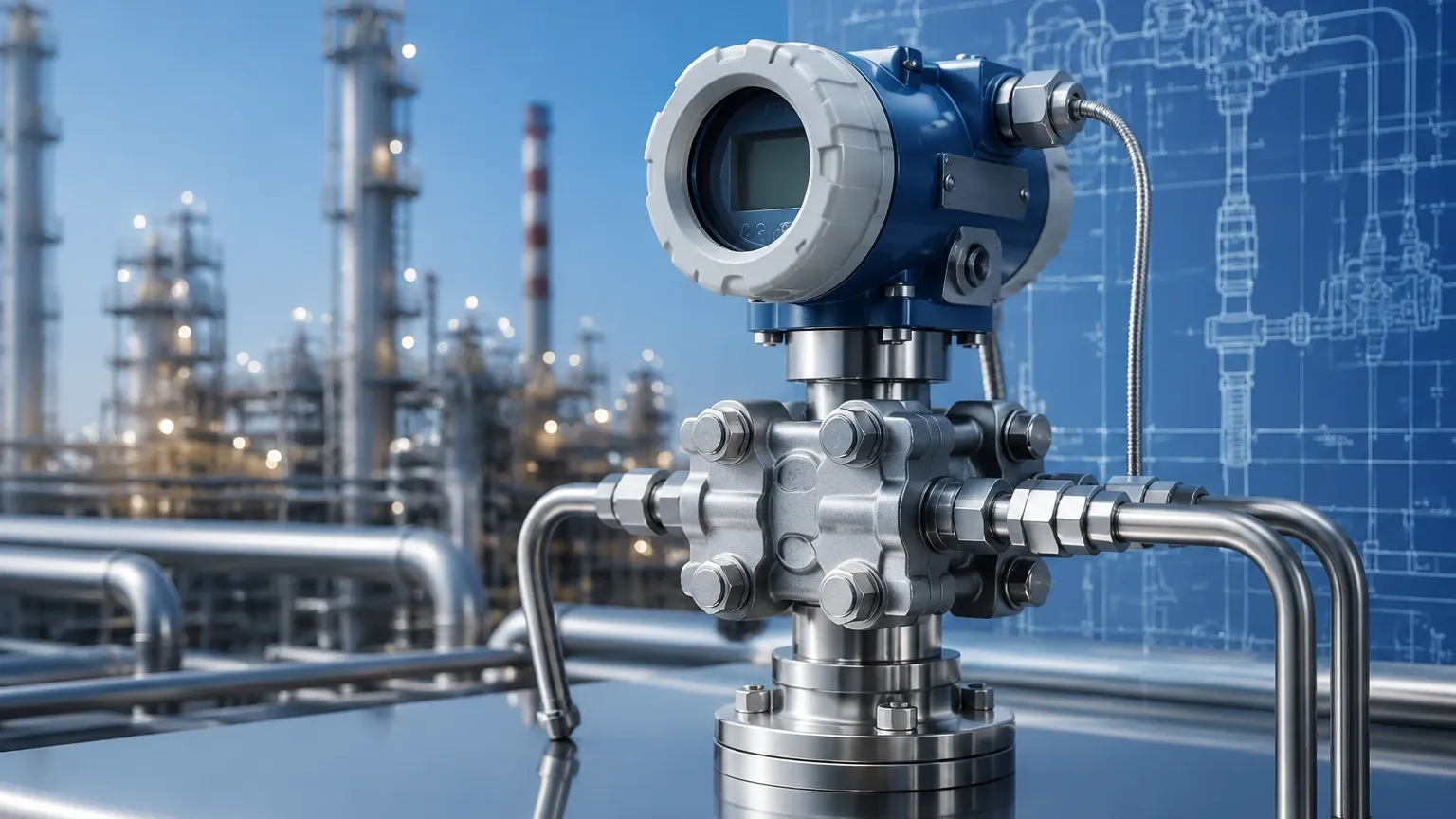
The differential pressure flow sensor is actually a system comprising two main parts: the primary element (which creates the pressure drop) and the secondary element (the DP transmitter that measures the pressure and converts it to a signal). Selecting the correct primary element is essential for application success.
1. Orifice Plates
The orifice plate is a thin metal disk with a precision-bored hole, usually centered, clamped between flanges. It is the most common primary element due to its low cost and ease of manufacture. However, it creates a significant permanent pressure loss because of the turbulence generated downstream.
2. Venturi Tubes
A Venturi tube consists of a converging conical section, a cylindrical throat, and a diverging recovery section. Because the fluid is gradually accelerated and decelerated, the permanent pressure loss is much lower than that of an orifice plate (often less than 10%). They are ideal for high-volume flows and fluids containing suspended solids, as the smooth profile prevents clogging.
3. Flow Nozzles
Flow nozzles act as an intermediate between orifice plates and Venturi tubes. They feature a curved inlet leading to a short cylindrical throat. They are particularly effective for high-velocity flows and erosive fluids, such as high-temperature steam, where an orifice plate might wear down quickly.
4. Pitot Tubes and Averaging Pitot Tubes
Unlike the previous elements that constrict the entire flow stream, a Pitot tube measures the difference between static pressure and impact (dynamic) pressure at a specific point. Averaging Pitot tubes feature multiple sensing ports across the pipe diameter to account for the flow profile, offering very low pressure drop but generally lower accuracy in turbulent conditions.
Selection Criteria for Industrial Applications
Choosing the right differential pressure flow sensor requires balancing technical requirements with budget constraints. Engineers must evaluate the following factors:
| Criteria | Orifice Plate | Venturi Tube | Flow Nozzle | Averaging Pitot |
| :— | :— | :— | :— | :— |
| Accuracy | ±0.5% to ±2% | ±0.5% to ±1.5% | ±1.0% | ±1.0% to ±2.0% |
| Pressure Loss | High | Very Low | Medium | Negligible |
| Relative Cost | Low | High | Medium | Medium |
| Suitability for Slurries | Poor | Excellent | Fair | Poor |
| Standardization | ISO 5167 / ASME | ISO 5167 / ASME | ISO 5167 | Manufacturer Specific |
For complex projects involving both flow and level monitoring, consulting a specialized manufacturer like Welk can ensure that the secondary DP transmitters are compatible with the primary elements. You can Review product options and application support to see how modern DP transmitters integrate with these primary devices.
Installation Considerations
The accuracy of a differential pressure flow sensor is highly dependent on the installation environment. Because the measurement relies on a stable flow profile, the following guidelines are critical:
* Straight Pipe Runs: To ensure a fully developed flow profile, the sensor must be preceded and followed by straight sections of pipe. Typically, a minimum of 10 to 20 pipe diameters upstream and 5 diameters downstream are required, depending on the type of upstream disturbances (e.g., elbows, valves, or pumps).
* Impulse Line Orientation: The impulse lines (the small-bore tubes connecting the primary element to the transmitter) must be installed correctly to prevent air or sediment traps.
* Gas Measurement: The transmitter should be mounted above the pipe so that any condensed liquid drains back into the process line.
* Liquid/Steam Measurement: The transmitter should be mounted below the pipe so that gas bubbles can rise back into the process line.
* Manifold Valves: A three-valve or five-valve manifold is essential. These allow the operator to isolate the transmitter for maintenance, equalize the pressure to check the zero-point calibration, and bleed air or liquid from the lines without shutting down the process.
Limitations and Risks
While robust, DP flow sensors are not without limitations. Understanding these risks is vital for long-term reliability:
1. Permanent Pressure Loss: The energy required to push fluid through a restriction is lost as heat and turbulence. In large-scale pumping operations, the cost of this energy loss over several years can exceed the initial cost of a more expensive, low-loss meter like an ultrasonic or magnetic flowmeter.
2. Viscosity Sensitivity: DP meters are sensitive to changes in the Reynolds number. If the fluid viscosity changes significantly (due to temperature fluctuations), the flow coefficient ($k$) may change, leading to measurement errors.
3. Square Root Turndown: As mentioned, the turndown ratio is typically limited to 3:1 or 4:1 for a single DP transmitter. While "stacked" transmitters (one for low DP and one for high DP) can extend this, it adds complexity and cost.
4. Wear and Fouling: The sharp edge of an orifice plate is critical for accuracy. Erosion from abrasive particles or the buildup of scale (fouling) will change the geometry of the restriction and cause the meter to drift over time.
Maintenance and Calibration
Maintenance of a differential pressure flow sensor system primarily focuses on the secondary element (the transmitter) and the integrity of the impulse lines.
* Zeroing: Periodically, the manifold valves should be used to equalize pressure across the transmitter to ensure it reads zero at zero flow. This compensates for sensor drift or mounting shifts.
* Impulse Line Flushing: In applications with dirty fluids, impulse lines can become plugged. Periodic flushing or the use of chemical seals (diaphragm seals) may be necessary.
* Primary Element Inspection: During plant shutdowns, primary elements like orifice plates should be inspected for edge sharpness and flatness. Even slight rounding of the upstream edge can result in an under-indication of flow.
Frequently Asked Questions (FAQ)
Q: Can a differential pressure flow sensor measure bidirectional flow?
A: Standard orifice plates and Venturi tubes are unidirectional. However, specialized bi-directional orifice plates or symmetrical primary elements can be used with a DP transmitter capable of measuring negative differential pressure.
Q: How does fluid density affect the measurement?
A: Since the DP sensor measures the pressure drop, which is a function of kinetic energy, the density of the fluid must be known to calculate the flow rate. If the density varies (e.g., in gas or steam applications due to pressure/temperature changes), "compensated flow" measurement is required using additional pressure and temperature sensors.
Q: What is the difference between a DP flow sensor and a hydrostatic level sensor?
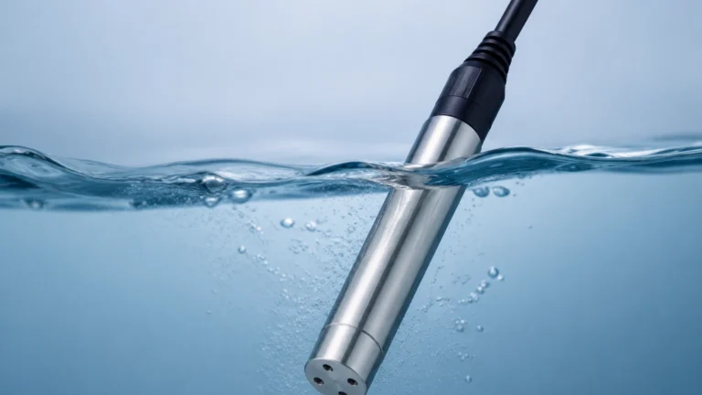
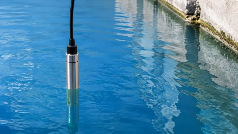
A: Both use the same secondary technology—a differential pressure transmitter. A flow sensor measures the pressure drop across a restriction, while a hydrostatic level sensor measures the pressure exerted by the weight of a liquid column. Companies like Welk provide transmitters that can be configured for either application.
Conclusion
The differential pressure flow sensor remains a fundamental tool in the engineer's arsenal for process control. By understanding the underlying physics of Bernoulli’s principle and carefully selecting the primary element based on the fluid properties and allowable pressure drop, users can achieve highly reliable and repeatable measurements. While installation requires precision—particularly regarding straight pipe runs and impulse line routing—the lack of moving parts and the extensive standardization of this technology ensure its continued relevance in modern industrial automation. For those seeking to integrate these sensors into a broader measurement strategy, exploring the full range of industrial instrumentation on the Main Page provides further insight into modern transmitter capabilities and customization options.