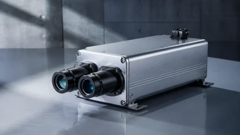
Ftl375p
Ftl375p
In the landscape of industrial process automation, the transition from a physical state—such as the presence of liquid in a tank—to a reliable electronic signal is a critical juncture. The ftl375p represents a specific category of signal conditioning and switching units designed to bridge this gap. Often utilized in conjunction with vibronic level sensors, these units serve as the "brain" in the control cabinet, interpreting the frequency changes of a tuning fork sensor and converting them into actionable relay outputs for overfill protection or dry-run prevention.
For engineers and procurement specialists, understanding the technical nuances of the ftl375p and its place within a broader level measurement strategy is essential for ensuring plant safety and operational efficiency. This guide examines the principles, selection criteria, and installation requirements for these switching units, while also providing context on how they integrate with modern industrial instrumentation found on the Main Page of leading measurement solution providers.
Measurement Principles: From Vibration to Switching
To understand the function of a unit like the ftl375p, one must first understand the principle of vibronic (tuning fork) level detection. This technology is widely regarded as one of the most reliable methods for point level detection in liquids, regardless of the fluid's dielectric constant, density, or turbulence.
The Sensor Side
A vibronic sensor consists of a tuning fork that is piezoelectrically excited to vibrate at its resonant frequency in the air. When the fork is submerged in a liquid, the frequency of vibration shifts due to the increased density of the medium surrounding the tines. This frequency shift is detected by the internal electronics of the sensor.
The Signal Conditioning Side
The ftl375p acts as the interface between the sensor in the field and the control system (PLC/DCS) in the rack room. Its primary functions include:
1. Power Supply: Providing the necessary intrinsically safe (Ex-i) power to the level sensor.
2. Signal Evaluation: Monitoring the current pulse or frequency signal coming from the sensor. A specific change in the signal indicates that the fork is either covered or uncovered.
3. Output Logic: Based on the evaluation, the unit toggles a relay (typically a DPDT or SPDT configuration). This can be set to "fail-safe high" (for overfill protection) or "fail-safe low" (for pump protection).
4. Line Monitoring: Advanced units like the ftl375p monitor the connection to the sensor for short circuits or cable breaks, ensuring that a fault in the wiring is not mistaken for a valid level state.
Key Technical Specifications of the Ftl375p Series
When evaluating a switching unit for a process plant, technical specifications dictate the compatibility with existing infrastructure. The ftl375p is typically characterized by its DIN rail mounting form factor, which allows for high-density installation in standard control cabinets.
Electrical Characteristics
* Supply Voltage: Most units support a wide range of AC/DC inputs, typically 20V to 253V AC/DC, providing flexibility for different regional power standards.
* Input Signal: Designed to interface specifically with PFM (Pulse Frequency Modulation) signals or 8/16mA current loops common in high-reliability level switches.
* Relay Outputs: Usually features two potential-free changeover contacts (DPDT). These are rated for specific loads, often up to 250V AC at 2A.
Safety and Certification
In the chemical and oil and gas industries, hazardous area certification is non-negotiable. The ftl375p is frequently used as an associated apparatus, meaning it sits in a non-hazardous area but provides an intrinsically safe circuit to a sensor located in Zone 0 or Zone 1. Common certifications include ATEX, IECEx, and SIL (Safety Integrity Level) ratings, typically SIL2 or SIL3 when used in redundant configurations.
Selection Table for Level Switching Units
Choosing the right signal conditioner requires a comparison of functional requirements. The following table outlines typical considerations for engineers selecting between different switching unit models.
| Feature | Standard Switching Unit | Advanced Signal Conditioner (e.g., ftl375p) | Integrated Sensor Logic |
| :— | :— | :— | :— |
| Mounting | DIN Rail (35mm) | DIN Rail (35mm) | Direct on Sensor |
| Input Type | Binary (On/Off) | PFM / 8/16mA | Piezoelectric Crystal |
| Safety Integrity | Non-SIL | SIL2 / SIL3 Capable | SIL2 Capable |
| Line Monitoring | No | Yes (Short/Break Detection) | Internal Only |
| Hazardous Area | No | Intrinsically Safe Interface | Explosion-Proof Housing |
| Output Type | Single Relay | Dual DPDT Relays | Transistor or 2-wire |
Installation Considerations and Wiring Protocols
Proper installation of the ftl375p is vital for maintaining the integrity of the safety loop. Because these units often handle intrinsically safe circuits, strict adherence to wiring standards is required.
Cabinet Placement
The unit should be mounted on a standard 35mm DIN rail. Given that these units can generate a small amount of heat during operation, it is recommended to maintain a minimum clearance of 5mm to 10mm between adjacent units to ensure adequate convection cooling. In high-density cabinets, active ventilation may be required if the ambient temperature exceeds 60°C (140°F).
Wiring and Separation
When wiring the ftl375p, installers must ensure a physical separation between the intrinsically safe (blue terminals) and non-intrinsically safe (grey or black terminals) wiring. This prevents high-voltage surges from jumping to the sensor circuit in the event of a fault. Use of shielded twisted pair cables is recommended for the sensor connection to minimize electromagnetic interference (EMI) from nearby heavy machinery or power cables.
Configuration of Fail-Safe Modes
One of the most critical steps during commissioning is setting the fail-safe mode.
* MAX (Overfill Protection): The relay de-energizes when the level rises above the sensor or when power is lost. This is the standard setting for tanks containing hazardous chemicals.
* MIN (Dry-run Protection): The relay de-energizes when the level falls below the sensor. This is used to protect pumps from running without fluid, which could cause mechanical seal failure.

Practical Applications in Process Industries
The utility of the ftl375p extends across various sectors where liquid level monitoring is a safety or operational priority.
Water and Wastewater Treatment
In large-scale water treatment plants, chemicals like sodium hypochlorite or alum are stored in bulk tanks. Using a vibronic switch paired with a signal conditioner like the ftl375p ensures that these tanks do not overflow, which would result in environmental contamination and regulatory fines. The reliability of the tuning fork technology means it is unaffected by the foam or bubbles often present in treatment processes.
Chemical Processing
In the chemical industry, the compatibility of the sensor material with the medium is paramount. While the ftl375p remains in the safe environment of the control room, the sensor it controls must withstand corrosive acids or bases. The switching unit provides a consistent interface regardless of whether the sensor is made of Stainless Steel, Hastelloy, or has a PFA coating.
Oil and Gas
For upstream and downstream oil applications, the ftl375p is often part of a larger safety instrumented system (SIS). Its ability to provide a SIL2 rated signal makes it suitable for high-risk environments where explosive vapors are present. The line monitoring feature is particularly valued here, as it alerts operators to cable damage caused by harsh environmental conditions or mechanical stress.
Limitations and Maintenance Requirements
While highly reliable, the ftl375p and its associated sensors are not without limitations.
1. Medium Buildup: If the sensor fork in the field experiences significant material buildup (e.g., highly viscous resins), the frequency shift may not be accurately detected. While the electronics in the ftl375p can sometimes be adjusted for sensitivity, physical cleaning of the sensor is the only permanent solution.
2. Electronic Aging: Like all solid-state electronics, the components within the switching unit have a finite lifespan, typically 10 to 15 years in a temperature-controlled environment. Periodic proof-testing is required in safety-critical applications.
3. Signal Distance: There are limits to the distance between the sensor and the ftl375p. Typically, distances up to 1000 meters (approx. 3280 feet) are possible with high-quality cabling, but excessive resistance or capacitance in the line can degrade the PFM signal.
Troubleshooting Common Issues
* Red LED Flashing: Usually indicates a fault detected by the line monitoring system. Check the field wiring for a short circuit or a disconnected wire at the sensor head.
* Relay Not Toggling: Verify that the supply voltage is within the specified range and that the fail-safe switch is in the correct position. If the sensor is covered but the relay does not move, check the sensor's vibration using a diagnostic tool or by observing the local LED on the sensor head (if equipped).
Integrating Advanced Level Measurement Solutions
While the ftl375p is a robust solution for point level switching, modern industrial automation often requires a combination of point level and continuous level measurement. For instance, a tank might use a radar level meter for continuous monitoring and a vibronic switch with a signal conditioner for high-high level alarms.
Welk provides a comprehensive range of instruments, including radar level meters, ultrasonic sensors, and hydrostatic transmitters, which can be viewed on our Main Page. By integrating these technologies, plant operators gain a multi-layered view of their processes, combining the precision of continuous measurement with the fail-safe reliability of point level switching.
Frequently Asked Questions (FAQs)
Q: Can the ftl375p be used with any tuning fork sensor?
A: No, it is specifically designed to work with sensors that output a compatible PFM or 8/16mA signal. Always check the manufacturer's compatibility matrix before pairing a sensor with a switching unit.
Q: What is the difference between a PFM signal and a standard relay output?
A: A PFM (Pulse Frequency Modulation) signal is a continuous stream of pulses where the frequency carries the status information. This is much more robust than a simple on/off voltage because it allows the ftl375p to monitor the health of the cable and the sensor in real-time.
Q: Is it possible to test the ftl375p without filling the tank?
A: Yes, most units feature a test button or a simulation input. Pressing the test button simulates a change in the sensor state, allowing the operator to verify that the relay toggles and the downstream alarms or pumps respond correctly.
Q: Does the ftl375p require software configuration?
A: Generally, no. Most units of this type are configured via physical DIP switches on the side or front of the housing. This makes them easy to replace in the field without the need for a laptop or specialized software.
Q: How does ambient temperature affect the unit?
A: The unit is designed for installation in control cabinets where temperatures typically range from -20°C to +60°C. If the cabinet is located outdoors in a hot climate, sunshields or cooling units should be used to prevent the internal electronics from overheating, which can lead to premature failure.
By understanding the specialized role of the ftl375p, engineering teams can better design safety loops that protect both personnel and assets. Whether for simple pump control or complex safety-instrumented systems, the combination of vibronic sensing and intelligent signal conditioning remains a cornerstone of industrial level management.