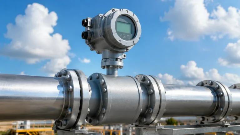
Fmu40
Fmu40
In the landscape of industrial process automation, the FMU40 represents a standard-setting solution for non-contact level measurement. As a compact ultrasonic transmitter, it is designed to bridge the gap between simple level detection and complex, long-range sensing requirements. This guide provides a technical deep dive into the operating principles, selection criteria, and engineering considerations essential for integrating FMU40 technology into modern industrial workflows.
Understanding Ultrasonic Level Measurement Principles
Before evaluating the specific capabilities of the FMU40, it is vital to understand the physics governing ultrasonic level measurement. This technology relies on the Time-of-Flight (ToF) principle, a method that calculates distance based on the speed of sound.
The Time-of-Flight (ToF) Mechanism
An ultrasonic sensor, such as the FMU40, contains a piezoelectric transducer that functions as both a transmitter and a receiver. The measurement cycle follows a specific sequence:
1. Emission: The transducer emits a high-frequency acoustic pulse (typically around 70 kHz for mid-range sensors).
2. Propagation: The sound wave travels through the medium (usually air or a gas buffer) toward the product surface.
3. Reflection: Upon hitting the surface of the liquid or solid, the acoustic energy is reflected back toward the sensor.
4. Detection: The transducer detects the returning echo and converts the mechanical vibration back into an electrical signal.
The distance ($D$) from the sensor reference point to the product surface is calculated using the formula:
$$D = \frac{c \times t}{2}$$
Where $c$ is the speed of sound in the medium and $t$ is the elapsed time between emission and reception. By subtracting this distance from the known empty height of the vessel, the transmitter determines the actual level of the material.
Temperature Compensation
The speed of sound is not constant; it fluctuates significantly with changes in air temperature. In a standard atmospheric environment, the speed of sound increases by approximately 0.6 meters per second for every degree Celsius increase. To maintain accuracy, the FMU40 incorporates an integrated temperature sensor. This allows the internal microprocessor to adjust the calculation in real-time, ensuring that seasonal or process-driven temperature swings do not result in measurement drift.
Technical Specifications and Performance of the FMU40
The FMU40 is characterized by its compact design and suitability for small to medium-sized vessels. It is frequently deployed in applications where mechanical contact with the medium is undesirable, such as in corrosive chemical tanks or wastewater basins.
Core Performance Parameters
* Measuring Range: Typically up to 5 meters (approx. 16 feet) for liquids and up to 2 meters (approx. 6.5 feet) for bulk solids. The reduced range for solids is due to the lower reflective properties of granular surfaces compared to flat liquid surfaces.
* Blocking Distance: Like all ultrasonic sensors, the FMU40 has a "dead zone" or blocking distance (typically 0.25 meters). Measurement is not possible within this range because the transducer cannot receive an echo while it is still vibrating from the initial pulse emission.
* Accuracy: Under reference conditions, the device maintains an accuracy of ±2 mm or 0.2% of the set measuring range.
* Frequency: Operating at approximately 70 kHz, the sensor provides a balance between resolution and the ability to penetrate minor dust or steam.
Material and Construction
The wetted parts of the FMU40 are generally constructed from chemically resistant materials such as PVDF (Polyvinylidene fluoride) with EPDM seals. This makes the device suitable for a wide array of acids, alkalis, and aqueous solutions. The housing is typically rated IP68, providing high-level protection against moisture ingress, which is critical for outdoor installations or wash-down environments.
Selection Criteria: When to Deploy FMU40 Technology
Selecting the right level instrument requires a comparison of the process requirements against the sensor's physical limitations. The FMU40 is an excellent choice for specific scenarios but may not be suitable for others.
Practical Selection Table
| Feature | FMU40 Capability | Engineering Consideration |
| :— | :— | :— |
| Medium Type | Liquids and coarse bulk solids | Fine powders may absorb sound waves. |
| Vessel Height | Up to 5 meters | Ensure the maximum level does not enter the blocking distance. |
| Process Pressure | 0.7 bar to 3 bar (abs) | Not suitable for high-pressure or vacuum applications. |
| Process Temperature | -40°C to +80°C | Accuracy depends on stable gas composition. |
| Output Signal | 4…20 mA HART | Compatible with most PLC and SCADA systems. |
Comparison with Radar Technology
While ultrasonic sensors like the FMU40 are cost-effective, engineers must decide between ultrasonic and radar (ToF using electromagnetic waves). Radar is preferred when the gas phase above the liquid is unstable (e.g., heavy foam, vacuum, or high-pressure steam), as electromagnetic waves are unaffected by air density. However, for standard atmospheric applications in water treatment or chemical storage, the FMU40 offers a more economical and simpler installation.
For professionals evaluating a broader range of measurement technologies, including advanced radar and guided wave options, reviewing a diverse product catalog is recommended. You can Review product options and application support to compare these technologies against specific project requirements.
Installation Guidelines for Optimal Signal Integrity
The reliability of an FMU40 installation is heavily dependent on the physical placement of the sensor. Incorrect mounting is the leading cause of "lost echoes" or false readings.
Positioning and Clearance
1. Avoid the Fill Stream: Never mount the sensor directly above the point where material enters the tank. The falling product will interfere with the ultrasonic pulse and cause erratic readings.
2. Wall Distance: The sensor should be mounted at a distance from the tank wall equal to at least 1/6th of the tank diameter. Mounting too close to the wall can result in "ringing" or interference from wall reflections.
3. Nozzle Geometry: If the sensor is mounted on a nozzle, the nozzle diameter must be large enough, and the nozzle height short enough, to ensure the ultrasonic beam does not hit the nozzle edge. The beam angle of the FMU40 is typically around 11 degrees.
4. Perpendicular Alignment: The transducer face must be parallel to the product surface. In liquid applications, this means the sensor must be perfectly vertical. For solids, an alignment swivel may be required to aim the sensor at the angle of repose.
Overcoming Internal Obstructions
Internal structures such as heating coils, ladders, or agitators can create false echoes. The FMU40's software typically includes an "echo mapping" or "fixed target suppression" feature. During commissioning, the engineer can record the echoes from these stationary objects and instruct the transmitter to ignore them, focusing only on the moving echo from the product surface.

Operational Limitations and Environmental Interference
While robust, the FMU40 has physical boundaries that, if crossed, will result in measurement failure.
* Heavy Foam: Thick, dense foam acts as an acoustic insulator, absorbing the ultrasonic pulse rather than reflecting it. If foam is a constant factor, a hydrostatic pressure transmitter or a radar sensor may be more appropriate.
* Vacuum Applications: Sound cannot travel in a vacuum. If the process involves a vacuum, the FMU40 will not function. Radar is the standard alternative here.
* High Turbulence: Rapidly agitating surfaces can scatter the ultrasonic signal. This can often be mitigated by using a standpipe (stilling well) to provide a calm surface for the measurement.
* Gas Composition: If the atmosphere in the tank is not air (e.g., high concentrations of CO2 or solvent vapors), the speed of sound will change significantly. Unless the gas composition is constant and the sensor is recalibrated for that specific medium, accuracy will suffer.
Application Profiles in Water and Process Industries
Wastewater Management
In wastewater treatment plants, the FMU40 is frequently used for level measurement in open channels, flumes, and weirs. Because it does not touch the liquid, it is immune to the fouling and debris common in sewage. It is often paired with an external controller to calculate flow rates based on the measured head (level) over a weir.
Chemical Storage
For small reagent tanks containing acids or cleaning agents, the PVDF construction of the FMU40 provides excellent longevity. It is often used in IBC (Intermediate Bulk Container) monitoring where a simple, top-mounted non-contact sensor is required for inventory management.
Food and Beverage
In non-hygienic auxiliary areas, such as water storage or CIP (Clean-In-Place) chemical recovery, the FMU40 provides a reliable, maintenance-free solution. However, for direct contact with food products, sensors with specific hygienic certifications (3-A, EHEDG) should be selected.
Maintenance, Troubleshooting, and Modern Alternatives
One of the primary advantages of the FMU40 is the lack of moving parts, which minimizes maintenance. However, periodic checks are recommended.
Troubleshooting Common Issues
* E101 / Signal Loss: Often caused by the level entering the blocking distance or heavy condensation on the transducer face. Ensure the sensor is mounted high enough to avoid the maximum level.
* Drifting Readings: Usually indicates a failure of the temperature compensation. Check the internal temperature reading via the HART interface to verify accuracy.
* Intermittent Spikes: Often caused by electromagnetic interference (EMI) from nearby high-power equipment or variable frequency drives (VFDs). Ensure the signal cable is shielded and grounded correctly.
The Role of Modern Equivalents
While the FMU40 remains a reliable workhorse, the industry has seen the rise of more versatile alternatives. Manufacturers like Welk offer a range of ultrasonic and radar sensors that provide enhanced signal processing and easier integration with IoT platforms. When upgrading or specifying new projects, it is beneficial to explore the latest Main Page offerings to ensure the chosen instrument meets modern efficiency and connectivity standards.
Frequently Asked Questions (FAQ)
Q: Can the FMU40 be used to measure the level of flour or fine powders?
A: It depends on the dust levels. While it can measure solids up to 2 meters, fine powders often create high dust during filling, which can attenuate the ultrasonic signal. Additionally, fine powders tend to absorb sound. A trial or a switch to radar is often recommended for very fine solids.
Q: How does condensation affect the FMU40?
A: Minor condensation on the transducer face is usually handled by the sensor's self-cleaning effect (the vibration of the transducer). However, heavy droplets can cause signal attenuation or a "blocked" sensor error. In high-humidity applications, a sensor with a drip-off transducer face design is preferred.
Q: What is the maximum cable length for the FMU40?
A: As a 4…20 mA HART device, the cable length can extend several hundred meters, provided the loop resistance is within the limits of the power supply and the cable is properly shielded to prevent signal degradation.
Q: Is it possible to calibrate the FMU40 without the medium present?
A: Yes. Since it is a Time-of-Flight sensor, you can perform a "dry calibration" by entering the empty and full distances into the device software via the local display or a HART communicator.
By following these technical guidelines and understanding the fundamental physics of ultrasonic measurement, engineers can successfully deploy the FMU40 to achieve accurate, reliable, and cost-effective level control in a variety of industrial environments.