
Ultrasonic Clamp-on
Ultrasonic Clamp-on
Ultrasonic clamp-on technology represents a significant advancement in non-invasive process measurement. Primarily utilized for liquid flow monitoring, this technology allows for the acquisition of critical process data without the need to penetrate pipe walls or interrupt industrial operations. For engineers and facility managers, understanding the nuances of ultrasonic clamp-on systems is essential for ensuring accuracy, longevity, and cost-effectiveness in demanding environments such as water treatment, chemical processing, and oil and gas production.
By leveraging the properties of acoustic waves, these instruments provide a versatile alternative to traditional wetted sensors. This guide explores the fundamental principles, selection criteria, installation protocols, and practical limitations of ultrasonic clamp-on technology within the broader context of industrial instrumentation.
Fundamental Principles of Ultrasonic Clamp-on Technology
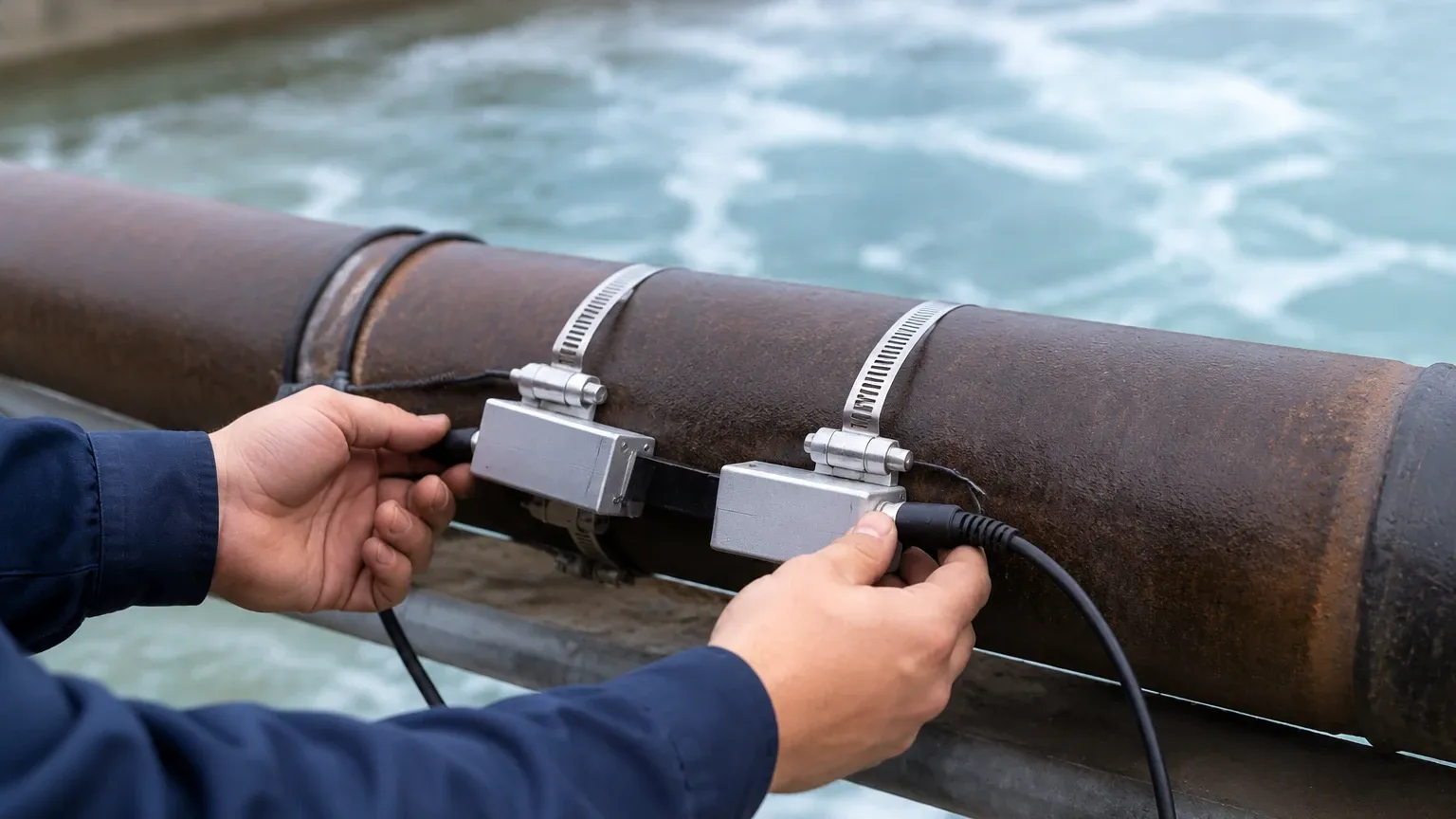
Ultrasonic clamp-on instruments operate by transmitting and receiving high-frequency sound waves through the pipe wall and the fluid medium. Unlike invasive sensors, the transducers are mounted externally. There are two primary measurement principles employed in these systems: Transit-Time and Doppler Effect.
Transit-Time Measurement
The transit-time method is the most common principle used for clean liquids. It relies on the difference in the time it takes for an ultrasonic pulse to travel between two transducers. One transducer transmits a signal upstream, while the other transmits downstream.
When the fluid is moving, the signal traveling with the flow (downstream) moves faster than the signal traveling against the flow (upstream). The electronics calculate the time difference (delta-t), which is directly proportional to the flow velocity. Because the cross-sectional area of the pipe is known, the system can accurately derive the volumetric flow rate. This method requires a relatively clean fluid with minimal solids or gas bubbles to ensure the signal can pass through the medium without excessive scattering.
Doppler Effect Measurement
The Doppler method is utilized for fluids containing suspended solids, bubbles, or high turbidity. In this configuration, a transducer sends a continuous ultrasonic signal into the fluid at a known frequency. This signal reflects off the moving particles or bubbles.
According to the Doppler principle, the frequency of the reflected signal shifts relative to the velocity of the particles. By measuring this frequency shift, the instrument determines the flow velocity. While generally less precise than transit-time meters for clean water, Doppler meters are indispensable for slurries, wastewater, and aerated liquids where transit-time signals would be completely attenuated.
Signal Propagation and Snell’s Law
A critical aspect of clamp-on technology is how the sound wave moves through different materials. As the ultrasonic pulse travels from the transducer, through the coupling agent, the pipe wall, any internal lining, and finally into the fluid, it undergoes refraction. Engineers must account for the speed of sound in each material and the angle of incidence, governed by Snell’s Law, to ensure the transducers are positioned correctly for the signal to be received by the opposing sensor.
Technical Specifications and Material Compatibility
The success of an ultrasonic clamp-on installation depends heavily on the physical characteristics of the piping system. Not all pipes are suitable for ultrasonic transmission, and certain materials present unique challenges.
Pipe Material Considerations
Standard industrial materials such as carbon steel, stainless steel, PVC, and copper are generally excellent conductors for ultrasonic waves. However, materials with high acoustic damping properties or non-homogeneous structures can be problematic.
* Ductile Iron: Often used in water distribution, ductile iron can have internal voids or inconsistent casting that scatters the ultrasonic signal.
* Concrete/Asbestos Cement: These materials are highly porous and usually attenuate sound waves to a degree that makes clamp-on measurement impossible.
* Composite Materials: Fiberglass or multi-layered plastic pipes require specific transducer frequencies to penetrate the varying densities of the material layers.
Internal Linings
Internal pipe linings significantly impact signal integrity. If a lining is well-bonded to the pipe wall (e.g., epoxy or thin rubber), the ultrasonic signal can pass through with minimal loss. However, if there is an air gap between the pipe and the liner—often found in older cement-lined pipes or loose-fit plastic sleeves—the signal will be reflected at the interface, resulting in a total loss of measurement. For more information on compatible measurement technologies for various tank and pipe configurations, you may visit the Main Page of our technical resource center.
Fluid Properties
While temperature and pressure do not directly stop the ultrasonic signal, they change the speed of sound in the fluid. Modern transmitters include temperature compensation algorithms, but users must input the correct fluid type (e.g., water, glycol, crude oil) so the device can reference the appropriate acoustic velocity tables.
Selection Criteria and Practical Comparison
When evaluating whether to use a clamp-on system versus an inline (wetted) meter, several factors must be weighed. The following table provides a comparison based on typical industrial requirements.
| Feature | Ultrasonic Clamp-on | Inline (Wetted) Meter |
| :— | :— | :— |
| Installation Cost | Low (No pipe cutting) | High (Requires shutdown/cutting) |
| Pressure Drop | Zero | Variable (Depends on type) |
| Maintenance | External only | Requires process shutdown |
| Accuracy | 0.5% to 2.0% of velocity | 0.2% to 1.0% of velocity |
| Fluid Compatibility | Most liquids | Limited by sensor material |
| Pipe Size Range | 15 mm to 6000 mm | Limited by flange size |
| Contamination Risk | Zero | Possible (Wetted parts) |
Installation Best Practices for Signal Integrity
The accuracy of an ultrasonic clamp-on meter is highly dependent on the quality of the installation. Even the most advanced transmitter cannot compensate for a poorly mounted transducer.
Surface Preparation
The exterior of the pipe must be cleaned to bare metal or smooth plastic. Rust, scale, and loose paint must be removed using a wire brush or grinder. The goal is to create a smooth, flat surface that allows for maximum acoustic contact.
Coupling Agents
Since air is an extremely poor conductor of high-frequency sound, a coupling agent (grease, gel, or a solid pad) must be used between the transducer face and the pipe wall. For permanent installations, high-viscosity silicone grease or specialized acoustic pads are preferred to prevent the couplant from drying out or washing away over time.
Mounting Configurations
There are three primary ways to orient the transducers, depending on the pipe diameter and fluid conditions:
1. V-Mode: The signal bounces off the opposite pipe wall once. This is the standard configuration for pipes ranging from 50 mm to 400 mm. It doubles the path length, increasing the time resolution and accuracy.
2. Z-Mode: Transducers are mounted on opposite sides of the pipe. The signal passes through the fluid only once. This is used for large-diameter pipes (above 400 mm) or pipes with high attenuation where a V-mode signal would be too weak.
3. W-Mode: The signal bounces three times. This is reserved for very small pipes (under 50 mm) where the transit time would otherwise be too short to measure accurately.
Straight Run Requirements
To ensure a stable flow profile, ultrasonic meters require a specific amount of straight pipe upstream and downstream of the installation point. Generally, a minimum of 10 pipe diameters (10D) upstream and 5 pipe diameters (5D) downstream is required. If the installation is near a pump or a partially open valve, these requirements may increase to 25D or more to avoid turbulence-induced errors.
Industrial Applications and Use Cases
Ultrasonic clamp-on technology is utilized across various sectors where process continuity is a priority. Welk provides specialized instrumentation that complements these flow solutions in complex industrial environments.
Water and Wastewater Management
In municipal water systems, clamp-on meters are frequently used for leak detection and pump station monitoring. Because they can be installed on very large pipes (up to 6 meters in diameter) without stopping the flow, they are the most cost-effective solution for retrofitting aging infrastructure.
Chemical and Petrochemical Processing
For corrosive, toxic, or high-pressure fluids, avoiding pipe penetration is a safety imperative. Clamp-on sensors do not have wetted parts, meaning there is no risk of chemical attack on the sensor or leaks at the mounting point. This makes them ideal for measuring acids, bases, and refined hydrocarbons.
HVAC and Energy Auditing
In building management, portable ultrasonic clamp-on meters are used to balance chilled water loops and conduct energy audits. Technicians can move the meter from one location to another to verify the performance of heat exchangers and pumps without installing permanent flow stations.
Limitations and Troubleshooting
Despite its versatility, ultrasonic clamp-on technology is not a universal solution. Engineers must be aware of specific limitations that can affect performance.
* Signal Attenuation: In very large pipes or fluids with high concentrations of suspended solids, the ultrasonic signal may be absorbed or scattered before it reaches the receiving transducer. Increasing the gain or switching to a lower frequency transducer can sometimes resolve this.
* Pipe Wall Interference: If the pipe wall is heavily corroded internally (pitting), the signal may scatter in unpredictable directions. In such cases, the reported "signal strength" on the transmitter will fluctuate or remain low.
* Ambient Noise: High-frequency vibration from nearby pumps or control valves can interfere with the ultrasonic signal. Shielding the cables and ensuring the transducers are mounted away from vibration sources is necessary.
* Aeration: Even a small percentage of entrained air (bubbles) can block transit-time signals. If the pipe is not completely full, or if there is significant cavitation, the meter will fail to provide a reading.
Frequently Asked Questions (FAQs)
Q: Can ultrasonic clamp-on meters measure gas flow?
A: While specialized clamp-on meters for high-pressure gas exist, they are significantly different from liquid meters. Most standard industrial clamp-on units are designed specifically for liquids. Gas measurement requires much higher signal amplification due to the low density of the medium.
Q: How often does the coupling gel need to be replaced?
A: For permanent installations using high-quality silicone couplant or solid pads, the interface can last for several years. However, in high-temperature applications or outdoor environments with extreme weather, it is recommended to inspect the signal strength annually and reapply couplant if a significant drop is observed.
Q: Does the pipe need to be full for an accurate reading?
A: Yes. Transit-time and Doppler clamp-on meters assume the pipe is 100% full to calculate the volumetric flow rate. If the pipe is partially full, the meter will over-calculate the flow because it assumes the entire cross-sectional area is occupied by liquid.
Q: Can I use clamp-on meters on pipes with thick cement linings?
A: It is difficult. Cement linings often contain air pockets or have a non-uniform structure that attenuates ultrasound. Success depends on the quality of the bond between the cement and the metal. A site test with a portable unit is always recommended before committing to a permanent installation on lined pipes.
Conclusion
Ultrasonic clamp-on technology offers a powerful, non-invasive method for process monitoring that aligns with the needs of modern industrial automation. By understanding the acoustic principles and adhering to strict installation guidelines, facilities can achieve reliable measurement data without the risks and costs associated with traditional pipe-cutting methods. Whether used for permanent monitoring in a chemical plant or as a diagnostic tool in water distribution, these instruments provide the flexibility and accuracy required for efficient process management. For those looking to integrate these sensors into a broader level and flow control strategy, consulting with a professional manufacturer like Welk ensures that the selected hardware meets the specific demands of the application environment.


