Radar Level Transmitter Ifm
Radar Level Transmitter Ifm: A Technical Guide to Selection and Application
In the landscape of industrial automation, precise level measurement is a cornerstone of process efficiency, safety, and inventory management. Among the various technologies available, non-contact radar has emerged as a preferred solution for demanding environments. Specifically, the radar level transmitter ifm series, known for its integration into IO-Link ecosystems and high-frequency operation, represents a significant evolution in how engineers approach liquid and bulk solid monitoring. This guide examines the underlying principles of radar technology, the specific advantages of 80 GHz systems, and the critical factors involved in selecting and installing these instruments in industrial settings.
1. Understanding Radar Measurement Principles
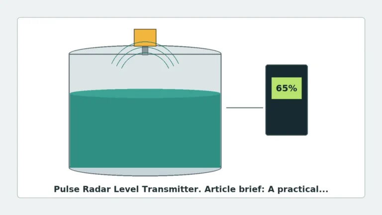
Before selecting a specific instrument, it is essential to understand how radar technology operates. Radar level measurement is based on the Time of Flight (ToF) principle. The sensor emits electromagnetic pulses or a continuous wave toward the medium. These waves are reflected by the surface of the material and received by the sensor antenna. The time elapsed between emission and reception is used to calculate the distance to the product surface.
Pulse Radar vs. FMCW Radar
Historically, industrial radar sensors were divided into two main categories: Pulse Radar and Frequency Modulated Continuous Wave (FMCW) radar.
* Pulse Radar: Emits short microwave pulses and measures the time delay. While effective, it often requires higher power for accuracy in turbulent conditions.
* FMCW Radar: This is the technology utilized by modern high-frequency units like the radar level transmitter ifm LW series. Instead of pulses, the transmitter sends a continuous signal with a constantly changing frequency. The difference in frequency between the emitted and reflected signal is proportional to the distance. FMCW provides superior signal-to-noise ratios, allowing for higher precision and better performance in tanks with internal obstructions.
For a broader look at available technologies, engineers often compare these systems with other Radar Level Meters to determine the best fit for specific dielectric properties and tank geometries.
2. The Advantages of 80 GHz High-Frequency Technology
The frequency at which a radar transmitter operates significantly impacts its performance. Older systems typically operated at 6 GHz or 26 GHz. The shift toward 80 GHz technology, found in many modern radar level transmitter ifm models, offers several distinct advantages for B2B industrial applications.
Focused Beam Angle
At 80 GHz, the wavelength is much shorter, which allows for a significantly narrower beam angle even with a small antenna size. A narrow beam is critical in narrow tanks or vessels with internal components like agitators, heating coils, or ladders. By focusing the energy into a tight beam, the sensor avoids "false echoes" from these obstructions.
High Dynamic Range
The dynamic range refers to the sensor's ability to detect weak signals from media with low dielectric constants (such as oils or plastic pellets) while still processing strong signals from water-based liquids. High-frequency radar provides better sensitivity, ensuring reliable measurement even when the surface is turbulent or covered in foam.
Compact Design and Hygienic Integration
Because the antenna can be smaller at higher frequencies, these transmitters are often more compact. In the food, beverage, and pharmaceutical industries, this allows for hygienic process connections (such as Tri-Clamp or Varivent) that meet EHEDG and 3-A standards.
3. Selection Criteria for Industrial Applications
Choosing the correct radar level transmitter requires a detailed analysis of the process environment. The following table outlines the primary selection parameters for industrial-grade radar sensors.
Selection Table: Radar Level Transmitter Parameters
| Parameter | Requirement/Range | Industrial Significance |
| :— | :— | :— |
| Measuring Range | Up to 10 m (32.8 ft) or 30 m (98.4 ft) | Determines suitability for small buffer tanks vs. large silos. |
| Dielectric Constant (εr) | > 1.1 | Determines the strength of the reflected signal. Low εr requires high-sensitivity radar. |
| Process Temperature | -40°C to +150°C (-40°F to 302°F) | Critical for CIP/SIP processes in food or chemical reactions. |
| Process Pressure | -1 to 16 bar (-14.5 to 232 psi) | Must match the vessel's structural ratings. |
| Communication | 4-20 mA, IO-Link, Modbus | Defines how the sensor integrates into the PLC/SCADA system. |
| Accuracy | ± 2 mm (0.08 in) | Essential for high-value inventory or precise dosing. |
4. Installation and Engineering Considerations
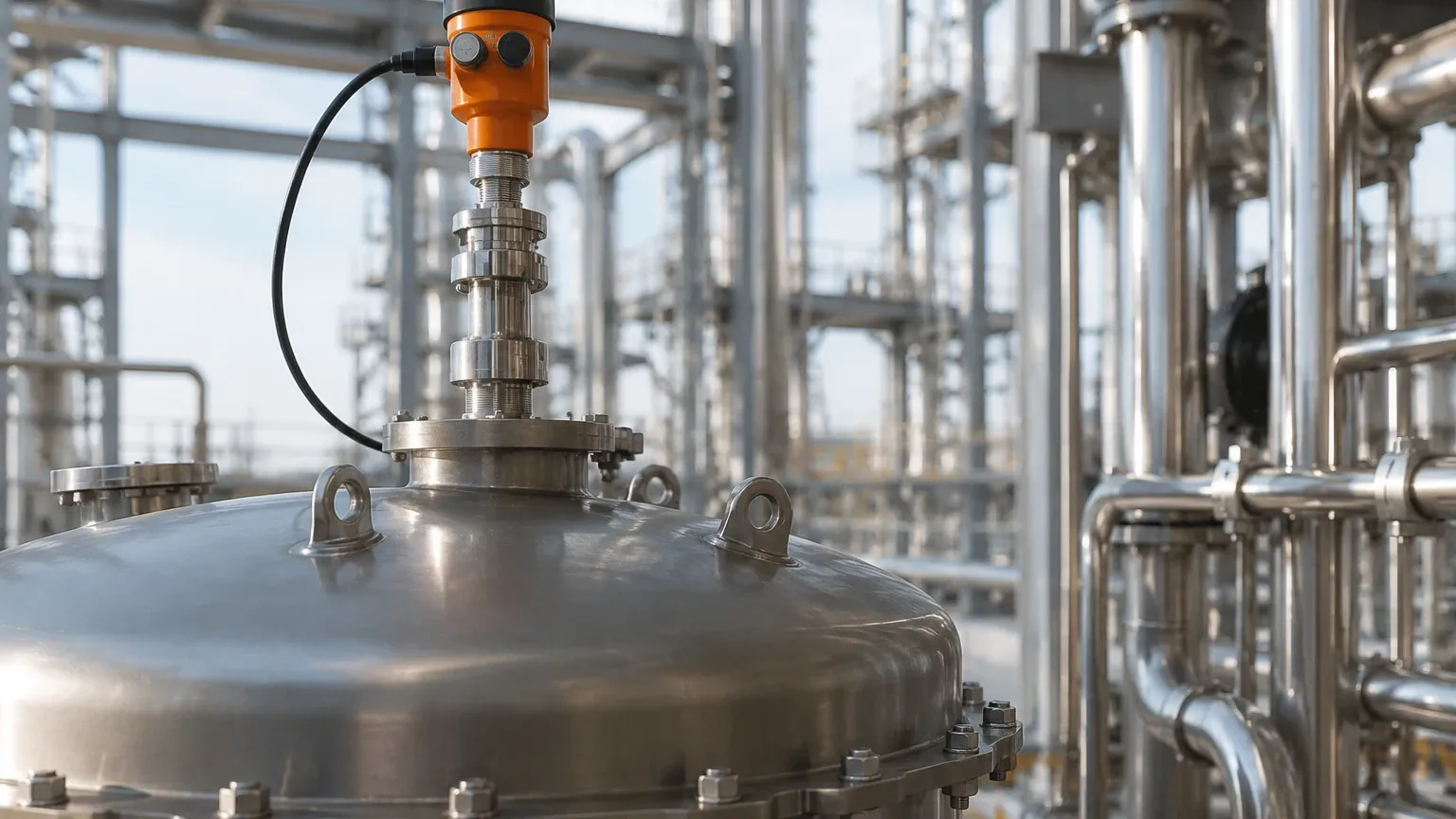
Even the most advanced radar level transmitter ifm will fail to perform if installed incorrectly. Engineering teams must adhere to specific mounting guidelines to ensure signal integrity.
Positioning and Nozzle Geometry
* Distance from Wall: The sensor should typically be mounted at 1/4 the diameter of the tank away from the wall to avoid interference from wall reflections.
* Nozzle Height: The antenna should ideally protrude slightly below the mounting nozzle. If the nozzle is too long or narrow, it can cause internal reflections that create a "blind zone" at the top of the tank.
* Obstructions: Ensure the beam path is clear of inflow streams and agitator blades. If an agitator is present, the software must be configured with a "false signal suppression" map.
The Dead Zone (Blind Zone)
Every radar sensor has a minimum measuring distance, often referred to as the dead zone or blocking distance. For many 80 GHz transmitters, this is relatively small (e.g., 50 mm to 150 mm), but it must be accounted for in tank volume calculations to prevent overfilling.
IO-Link Integration
A defining feature of the radar level transmitter ifm is its native IO-Link capability. This allows for digital data transmission, which is immune to electromagnetic interference (EMI). Furthermore, IO-Link enables remote parameterization and diagnostic monitoring, such as tracking the signal quality (echo ratio) to predict when cleaning may be required.
5. Limitations and Application Risks
While radar is highly versatile, it is not a universal solution. Engineers must be aware of specific conditions that can attenuate or scatter the radar signal.
1. Heavy Foam: While 80 GHz radar can penetrate some light foam, extremely dense, dry foam (like shaving cream) can absorb the microwave signal entirely, leading to signal loss.
2. Extremely Low Dielectric Media: Non-polar liquids like liquid nitrogen or certain pure hydrocarbons have very low reflectivity. In these cases, a guided wave radar (GWR) or a high-sensitivity Radar Level Meters solution may be necessary.
3. Heavy Condensation or Buildup: If the medium is prone to heavy coating (e.g., thick syrups or resins), the antenna face may become obscured. While many 80 GHz units have a "drip-off" lens design, severe buildup will eventually require manual cleaning or an air purge system.
6. Buyer’s Checklist for International Procurement
When sourcing a radar level transmitter ifm or equivalent industrial instrumentation for global projects, procurement officers should confirm the following technical details with the manufacturer:
* Certification: Does the unit carry ATEX/IECEx for hazardous zones? Does it meet FDA/3-A for hygienic use?
* Housing Material: Is the housing 316L stainless steel for corrosive environments, or is a high-grade plastic sufficient?
* Interface Requirements: Is a local display required for manual checks, or will all data be handled via a digital bus?
* Configuration Tools: Is specialized software required for calibration, or can it be configured via standard IO-Link masters?
7. Frequently Asked Questions (FAQ)
Q: Can radar transmitters measure solids and liquids?
A: Yes, but the surface profile of solids (angle of repose) requires a sensor with a high dynamic range and often a different mounting angle to ensure the signal returns to the antenna.
Q: How does temperature affect radar accuracy?
A: Unlike ultrasonic sensors, radar waves are electromagnetic and do not rely on air density. Therefore, changes in air temperature, pressure, or vapor composition have negligible effects on the speed of the signal and the resulting accuracy.
Q: Is 80 GHz always better than 26 GHz?
A: For most small to medium tanks and hygienic applications, 80 GHz is superior due to the narrow beam. However, 26 GHz may still be used in very large silos where a slightly wider beam can help average out the uneven surface of bulk solids.
Q: What is the maintenance schedule for a non-contact radar?
A: Because there are no moving parts and no contact with the media, maintenance is minimal. Periodic checks of the antenna face for buildup and verification of the signal strength via the control system are usually sufficient.
By following these engineering guidelines and understanding the technical nuances of the radar level transmitter ifm, industrial operators can ensure reliable, long-term level monitoring in even the most challenging process conditions.