Radar Level Transmitter Instrumentation Tools
Radar Level Transmitter Instrumentation Tools: A Technical Engineering Guide
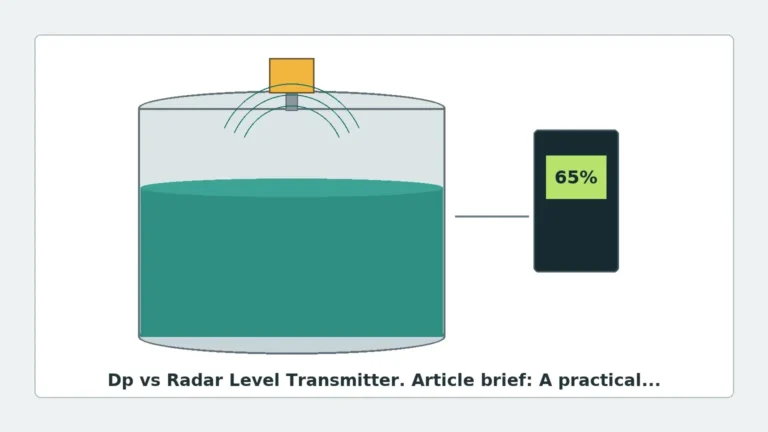
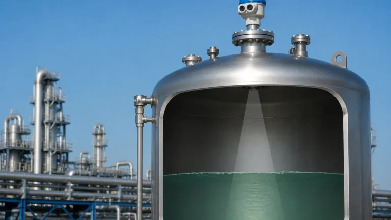
In the landscape of modern industrial automation, the ability to accurately monitor liquid and solid levels in storage tanks and process vessels is critical for safety, efficiency, and inventory management. Among the various technologies available, radar level transmitter instrumentation tools have emerged as the premier choice for challenging environments. Utilizing microwave technology, these instruments provide non-contact or guided measurement solutions that remain largely unaffected by changes in temperature, pressure, or the presence of dust and vapor.
This guide explores the underlying physics of radar measurement, compares different technical configurations, and provides a practical framework for selecting and installing Radar Level Meters in industrial settings.
1. Understanding Radar Measurement Principles
Before selecting a specific radar level transmitter, it is essential to understand the two primary methods used to process microwave signals: Time of Flight (ToF) and Frequency Modulated Continuous Wave (FMCW).
1.1 Time of Flight (Pulsed Radar)
Pulsed radar instruments emit short microwave pulses toward the surface of the medium. These pulses travel at the speed of light, reflect off the product surface, and return to the sensor's antenna. The instrument measures the time elapsed between emission and reception. Since the speed of light is constant, the distance ($D$) is calculated as:
$$D = \frac{c \times t}{2}$$
Where $c$ is the speed of light and $t$ is the measured time. Pulsed radar is often preferred for applications where power consumption must be minimized, such as battery-powered or loop-powered remote monitoring stations.
1.2 Frequency Modulated Continuous Wave (FMCW)
FMCW radar does not send discrete pulses. Instead, it emits a continuous signal with a frequency that changes linearly over time (a frequency sweep). When the reflected signal is received, it is compared to the signal currently being emitted. The difference in frequency ($\Delta f$) is directly proportional to the distance the signal has traveled.
FMCW technology is generally more accurate than pulsed radar and provides better signal-to-noise ratios, making it the standard for high-precision custody transfer and complex process vessels with internal obstructions.
2. Guided Wave Radar (GWR) vs. Non-Contact Radar
Radar level transmitter instrumentation tools are categorized into two physical formats based on how the microwave signal is transmitted to the media.
2.1 Non-Contact (Free-Space) Radar
These instruments emit microwaves through the air via an antenna (horn, parabolic, or lens type). They are ideal for corrosive media because the instrument does not touch the material.
* Advantages: No wear and tear, handles extremely high temperatures (up to 450°C), and is suitable for moving parts like agitators if positioned correctly.
* Disadvantages: Signal can be weakened by heavy foam or extremely low dielectric constants ($\epsilon_r$).
2.2 Guided Wave Radar (GWR)
GWR uses a physical probe (cable or rod) to guide the microwave pulse directly to the surface. This concentrated path ensures that more energy reaches the product and returns to the sensor.
* Advantages: Excellent for low dielectric liquids (like oils and liquefied gases), unaffected by turbulence or foam, and capable of measuring the interface between two liquids (e.g., oil and water).
* Disadvantages: The probe is in contact with the medium, making it susceptible to coating, corrosion, or mechanical stress from heavy solids.
3. Technical Selection Criteria: Frequency and Dielectrics
When evaluating radar level transmitter instrumentation tools, the frequency of the instrument is a decisive factor in performance.
3.1 The Impact of Frequency
* 6 GHz (C-Band): Lower frequency radars have longer wavelengths. They are less affected by steam, heavy dust, or condensation on the antenna. However, they have a wide beam angle, requiring larger tanks to avoid interference from walls.
* 26 GHz (K-Band): The industry standard for many years. It offers a balance between a manageable beam angle (approx. 8° to 12°) and resistance to process conditions.
* 80 GHz (W-Band): The modern benchmark for precision. 80 GHz radar features a very narrow beam angle (as small as 3°), allowing it to measure in tall, narrow tanks or vessels with many internal obstructions like cooling coils and ladders.
3.2 Dielectric Constant ($\epsilon_r$)
The dielectric constant of the material determines how much of the radar signal is reflected.
* High $\epsilon_r$ (> 10): Water-based liquids provide strong reflections and are easy to measure.
* Low $\epsilon_r$ (1.4 – 4): Hydrocarbons, solvents, and solids provide weak reflections. In these cases, high-sensitivity 80 GHz non-contact radar or Guided Wave Radar is required.
4. Selection Table for Industrial Applications
| Application Type | Recommended Radar Type | Frequency | Key Benefit |
| :— | :— | :— | :— |
| Water Treatment (Open Channels) | Non-contact | 26 GHz / 80 GHz | Maintenance-free, IP68 protection |
| Chemical Storage (Corrosive) | Non-contact (PTFE Lens) | 80 GHz | Chemical resistance, narrow beam |
| Oil/Water Interface | Guided Wave (GWR) | 1-10 GHz | Accurate detection of layer separation |
| Cement/Grain Silos | Non-contact | 26 GHz / 80 GHz | Penetrates dust, high range (up to 120m) |
| Small Process Vessels | Non-contact | 80 GHz | Avoids internal obstructions |
| High-Pressure Boilers | Guided Wave (GWR) | 1-10 GHz | Unaffected by steam/density changes |
5. Installation Considerations and Best Practices
Proper installation is critical to the reliability of radar level transmitter instrumentation tools. Even the most advanced sensor will fail if the signal path is compromised.
1. Nozzle Height and Diameter: The antenna should ideally extend slightly beyond the mounting nozzle to prevent signal ringing within the nozzle itself. If using an 80 GHz unit, nozzle interference is minimized due to the narrow beam.
2. The 1/6th Rule: For cylindrical tanks, the instrument should be installed at approximately 1/6th of the tank diameter from the side wall. Installing it too close to the wall causes reflections from the shell; installing it in the center can cause multiple bounce interference in domed-roof tanks.
3. Avoiding Obstructions: Ensure the signal beam does not intersect with ladders, agitator blades, or inflow streams. If obstructions are unavoidable, most modern radars offer "False Signal Suppression" or "Echo Mapping" to ignore static reflections.
4. Dead Zones (Blocking Distance): Every radar has a minimum measuring distance (typically 50mm to 300mm from the antenna). The tank should never be filled into this zone, as the reading will become non-linear or lost.

6. Limitations and Application Risks
While highly versatile, radar level transmitter instrumentation tools have specific limitations that engineers must account for:
* Heavy Foam: Extremely thick, dense foam (like shaving cream) can absorb the microwave signal entirely, leading to a "Loss of Echo." In such cases, GWR or ultrasonic sensors (depending on the foam density) may be required.
* Vacuum Conditions: While radar works in a vacuum, the mechanical seals of the instrument must be rated for vacuum to prevent air ingress or sensor damage.
* Extreme Turbulence: Rapidly moving liquid surfaces can scatter the radar signal. This is mitigated by using GWR or by increasing the damping (averaging) time in the transmitter software.
* Condensation and Buildup: While 80 GHz units handle thin films well, heavy crystalline buildup on the antenna will attenuate the signal. Integrated air purge systems can be used to keep the antenna face clean.
7. Procurement Checklist for International Buyers
When sourcing radar level transmitter instrumentation tools for global projects, confirm the following technical specifications with the manufacturer:
1. Process Connection: Specify thread types (G, NPT) or flange standards (ANSI, DIN, JIS).
2. Output Protocol: Standard 4-20mA is common, but HART, Modbus RS485, or Foundation Fieldbus may be required for integration into a PLC/DCS.
3. Hazardous Area Ratings: Confirm if the site requires ATEX, IECEx, or UL/CSA certifications for explosive atmospheres (Ex ia or Ex d).
4. Material Compatibility: Ensure the wetted parts (316L Stainless Steel, PTFE, PEEK) are compatible with the process media.
5. Accuracy Requirements: Standard industrial accuracy is ±2mm or ±3mm, but custody transfer applications may require ±0.5mm.
8. Frequently Asked Questions (FAQ)
Q: Can radar measure the level of solids like sand or plastic pellets?
A: Yes. Non-contact radar is excellent for solids. However, because solids often have an angle of repose (sloped surface), a high-frequency (80 GHz) radar with a swiveling flange is often used to align the beam for the best reflection.
Q: Is radar better than ultrasonic level measurement?
A: In most industrial B2B applications, yes. Ultrasonic sensors rely on sound waves, which are affected by air temperature, pressure, and wind. Radar uses electromagnetic waves, which are much more stable in varying process conditions.
Q: How do I handle a tank with a heavy agitator?
A: Use a radar with a narrow beam angle (80 GHz) and position it away from the blades. Additionally, use the software's "False Signal Suppression" to map out the agitator reflections while the tank is empty.
Q: Does the color of the liquid affect the measurement?
A: No. Radar is an electromagnetic measurement; color, transparency, and light levels have zero impact on the accuracy of the instrument.
Conclusion
Radar level transmitter instrumentation tools represent the pinnacle of current level sensing technology. By understanding the nuances between FMCW and Pulsed signals, and by correctly matching the frequency and physical format (GWR vs. Non-contact) to the specific medium, engineers can ensure long-term, maintenance-free operation. For complex environments involving high pressures, corrosive chemicals, or narrow geometries, Radar Level Meters provide the reliability necessary to maintain process safety and operational continuity.
Download Radar Level Transmitter Instrumentation Tools as a PDF